


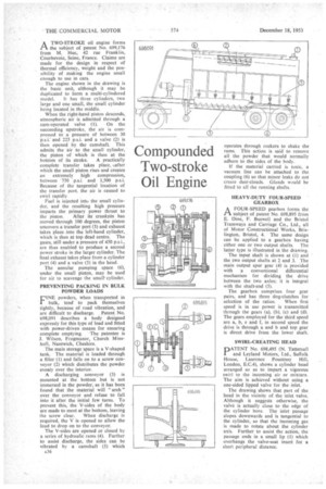
Compounded Two-stroke Oil Engine
Page 62
If you've noticed an error in this article please click here to report it so we can fix it.
A TWO-STROKE oil engine forms Pi the subject of patent No. 699,176 from M. Hue, 42 rue Franklin, Courbevoie, Seine, France. Claims are made for the design in respect of thermal efficiency, weight and the possibility of making the engine small enough to use in cars.
The engine shown in the .drawing is the basic unit, although it may be duplicated to form a multi-cylindered model. It has three cylinders, two large and one small, the small cylinder being located in the middle.
When the right-hand piston descends, atmospheric air is admitted through a cam-operated valve (1). On the succeeding upstroke, the air is compressed to a pressure of between 30 p.s.i. and 225 p.s.i. and a valve (2) is then opened by the camshaft. This admits the air to the small cylinder, the piston of which is then at the bottom of its stroke. A practically complete transfer takes place, after which the small piston rises and creates an extremely high compression, between 750 p.s.i. and 1,500 p.s.i. Because of the tangential location of the transfer port. the air is caused to swirl rapidly.
Fuel is injected into the small cylinder, and the resulting high pressure imparts the primary power thrust to the piston. After its crankpin has moved through 100 degrees, the piston uncovers a transfer port (3) and exhaust takes, place into the left-hand cylinder, which is then at top dead centre. The gases, Still under a pressure of 450 p.s.i., are thus enabled to produce a second power stroke in the larger cylinder. The final exhaust takes place from a cylinder port (4) and a valve (5) in the head.
The annular pumping space (6), under the small piston, may be used for air to scavenge the smalt•cylinder.
PREVENTING PACKING IN BULK POWDER LOADS
.FINE powders, when transported in bulk, tend' to pack themselves tightly, because of road vibration, and
are difficult to discharge. Patent No. 698,091 describes a body designed expressly for this type of load and fitted with power-driven means for ensuring complete emptying. The patentee is .1. Wilson, Frogmanor, Church Minshull, Nantwich, Cheshire.
The main storage space is a V-shaped tank. The material is loaded through a filler (I) and falls on to a screw Conveyor (2) which distributes the powder evenly over the interior.
A discharging conveyor (3) is mounted at the bottom but is not immersed in the powder; as it has been found that the material will " arch " over the conveyor and refuse to fall into it after the initial few turns. To prevent this, the V-sides of the body are made to meet at the bottom, leaving the screw clear. When discharge is required, the V is opened to allow the load to drop on to the conveyor.
The V-sides are opened or closed by a series of hydraulic rams (4). Further to assist discharge, the sides can be vibrated by a camshaft (5) which A36 operates through rockers to shake the rams. This action is said to remove all the powder that would normally adhere to the sides of the body.
If the material carried is toxic, a vacuum line can be attached to the coupling (6) so that minor leaks do not create dust-clouds. Glands would be fitted to all the running shafts HEAVY-DUTY FOUR-SPEED GEARBOX
A FOUR-SPEED gearbox forms the ti 'subject of patent No. 698,895 from E. Dine, F. Buswell and the Bristol Tramways and Carriage Co., Ltd., all of Motor Constructional Works, Bristington, Bristol, 4. The same design can be applied to a gearbox having either one or two output shafts. The latter type is illustrated in the drawing.
The input shaft is shown at (1) and ' the two output shafts at 2 and 3. The main output spur gear (4) is provided with a conventional differential mechanism for dividing the drive between the two axles; it is integral with the shaft-end (5).
The gearbox comprises four gear pairs, and has three dog-clutches for selection of the ratios. When first speed is in use power is transmitted through the gears (a), (b), (c) and (d). The gears employed for the third speed are a, b, c and f, in second speed the drive is through a and b and top gear is direct drive from the lower shaft.
SWIRL-CREATING HEAD
PATENT No. 698,495 (N. Tattersall and Leyland Motors, Ltd., Suffolk House, Laurence Pountney Hill, London, E.C.4), shows a cylinder head arranged so as to impart a vigorous swirl to the incoming air or mixture. The aim is achieved without using a one-sided lipped valve for the inlet.
The drawing shows that part of the head in the vicinity of the inlet valve. Although it suggests otherwise, the valve is actually close to the edge of the cylinder bore. The inlet passage slopes downwards and is tangential to the cylinder, so that the incoming gas is made to rotate about the cylinder axis. Further to assist the action, the passage ends in a small lip (1) which overhangs the valve-seat insert for a short peripheral distance.