


A.E.C. Cylinder-head Improvement
Page 54
If you've noticed an error in this article please click here to report it so we can fix it.
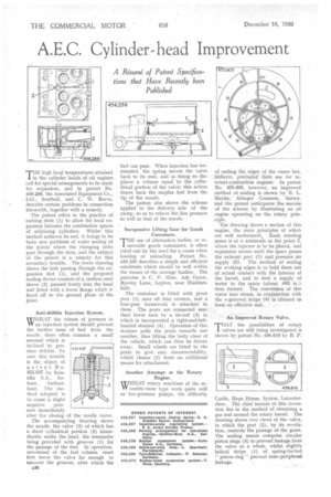
A Resume of Patent Specifications that Have Recently been Published THE high local temperatures attained in the cylinder heads of oil engines call for special arrangements to be made for expansion, and in patent No. 456,289, the Associated Equipment Co., Ltd., Southall, and C. W. Reeve, describe certain problems in connection therewith, together with a remedy.
The patent refers to the practice of cutting slots (1) to allow for local expansion between the combustion spaces of adjoining cylinders. Whilst this method achieves its end, it brings in its train new problems of water sealing at the points where the clamping bolts pass through the slots, and the subject of the patent is a remedy for this secondary trouble. The lower drawing shows the bolt passing through the expansion slot (1), and the proposed sealing device consists of a rustless steel sleeve (2) pressed firmly into the bead and fitted with a lower .flange which is faced off to the general plane of the joint.
Anti-dribble Injection System.
WHILST the release of pressure in VV an injection system should prevent the further issue of fuel from the nozzle, there often remains a small amount which is inclined to produce dribble. To cure this trouble is the object of patent No. 455,637 by Scintilla S.A., So
tense, Switzerland. The method adopted is to cause a slight negative pressure immediately after the closing of the needle valve.
The accompanying drawing shows the nozzle, the valve (3) of which has a short cylindrical portion (2) immediately under the head, the remainder being provided with grooves (1) for the passage of the fuel. In operation, movement of the fuel column must first move the valve far enough to uncover the grooves, after which the
455657
fuel can pass. When injection has terminated, the spring moves the valve back to its seat, and in. doing so dis-7 places a volume equal to the cylindrical portion of the valve; this action draws back the surplus fuel from the tip of the nozzle.
The patent also shows the scheme applied to the delivery, side of the pump, so as to relieve the line pressure as well as that of the nozzle.
inexpensive Lifting Gear for Goods Containers.
THE use of alternative bodies, or removable goods containers, is often ruled out by the need for a crane when loading or unloading. Patent No. 456,259 describes a simple and efficient substitute which should be well within -the means of the average haulier. The patentee is C. P. Hine, Ash Grove, R9wley Lane, Lepton, near Huddersfield.
The container is fitted with pivot pins (1) near all four corners, and .a four-post framework is • attached to these. The posts are connected near their lower ends by a tie-rod (3) in which is incorporated a right-and-lefthanded strainer (4). Operation of this strainer pulls the posts towards one another, thus lifting the body clear of the vehicle, which can then be driven away. Small wheels are fitted to the posts to give easy manceuvrability, whilst chains (2) form an additional means for attachment.
Another Attempt at the Rotary Engine. • WHILST rotary machines of the eel'', centric-vane type work quite well as low-pressure puffins, the difficulty of sealing the edges of the vanes has, hitherto, preeluded their use for internal-combustion engines. In patent No. 455,805, however, an improved method of sealing is shown by B. L. Martin, Abinger Common, Surrey, and the patent anticipates the success of the scheme by illustrating an oil engine operating on the rotary principle.
The drawing Shows a section of this engine, the main principles of which are well understood. Each rotating space is at a minimum at the point 3. where the injector i.s to be placed, and expansion occurs until the space passes
exhaust port (1) and pressure air supply (2). The method of sealing the working edges is to hold them out of actual contact with the interior of the barrel, and to feed a supply of water to the space (about .002 in.) thus formed. The conversion of this water into steam, in conjunction with the v-grooved strips (4)` is. claimed to form an effective seal.
An Improved Rotary Valve.
THAT the possibilities of rotary valves are still being investigated is shown by patent No. 456,610 by R. P.
Castle, Hope House, Syston, Leicester shire. The chief feature of this invention lies in the method of obtaining a gas seal around the rotary barrel. The drawing shows two views of the valve, in which the port (2), by its revolution, controls the passage of the gases. The sealing means comprise circular piston rings (3) to prevent leakage from the valve as a whole, whilst slightly helical Strips (1) of spring-backed " piston-ring " prevent inter-peripheral leakage.