New Hydraulically Controlled
Page 45

If you've noticed an error in this article please click here to report it so we can fix it.
Mechanical Servo Brake
Lockheed-Gates System in which a Friction Clutch Amplifies the Braking Force in Exact Proportion to Pedal Pressure. Ingenious System of Establishing Equilibrium
T0 employ the kinetic energy of a moving vehicle as the source of power to apply the brakes to brine'° the vehicle to rest, or to retard its progress, seems an obvious procedure. One method of doing this is to use a shoe mechanism of the self-energizing type and this is highly successful within limits.
Another is to take power from the transmission, but, although engineers have been devoting considerable attention to this scheme for several decades, the fact remains that no mechanical system is standardized to-day on any British commercial vehicle. Now a device has been evolved which combines a friction clutch with an hydraulic controlling apparatus.
This is the Lockheed-Gates " Straight Line" brake servo system, marketed by the Automotive Products Co., Ltd., Brock House, Laugh= Street, London, W.1. • A representative of this paper has had a brief experience of its capabilities as the braking system of a laden 3-ton lorry and reports that it seemed progressive and sensitive to pressure, also that a distinctly moderate effort was necessary to apply the brakes effectively. We hope, in the near future, to subject it to a more comprehensive trial than has hitherto been practicable.
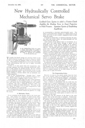
The accompanying sectional view of the Lockheed-Gates apparatus shows it installed behind the gearbox of a large bus chassis.
A Multi-plate Clutch.
On an extension of the gearbox shaft is the clutch portion. This consists of a number of small friction discs, splined to the shaft and positioned alternately with castiron annular members, provided each with a cooling fin. Through holes in the last-named passes a number of driving pins, the forward ends of which are screwed into a carrier which also forms the end plate of the clutch. This is mounted on a bakelite-graphite self-lubricating bush. At the rear end of the clutch and separated from it by a thrust piece of similar material is a pressure plate.
Around the carrier a groove is formed, and to it is attached a chain, which can wrap around the carrier in the groove. The direction of wrapping depends upon whether the vehicle is travelling forwards or backwards.
It will be observed that the other end of the chain is wrapped around a similarly grooved part, and that the hub of this, which we will refer to later as the nut, is threaded to accommodate a two-start quick-threaded screw. The latter is prevented from rotating by a splined block on its shaft, but is free to move axially, causing the block to slide along the casing.
It should be noted that, in whichever direction the gearbox shaft and carrier rotate, the quick-threaded nut will always turn the same way.
Axial motion of the splined block is transmitted, by a stout push rod which passes through a gland, to an hydraulic piston in the master cylinder of an ordinary Lockheed system. Both sides of this piston, however, are effective. The forward part of the cylinder is in communication with a further and smaller cylinder operated by the brake pedal. Moreover, fluid can flow from this forward chamber by pipes leading to two small cylinders containing plungers that abut against the clutch pressure plate.
Before considering the action of the device, it should be mentioned that the air-cooling arrangements of the clutch, referred to previously, are patented, and constitute a matter of considerable importance. It is claimed that in no circumstances can the servo gear exceed a safe temperature, thus the need for reduction gearing is removed.
In operation, an initial pressure is set up in the front end of the master cylinder by pedal pressure. This is communicated, via the two small plungers, to the pressure plate and energizes the clutch, causing a torwe to be transmitted by the chain to the quick-thread nut. The effect of this is to impose pressure on the fluid behind the master piston, and to apply the brakes.
The Compensating Action.
However, so soon as the piston recedes from the front end of the cylinder, there is a pressure drop in the servo line, and on the clutch-energizing plungers. Accordingly, further application of the brakes ceases until additional force be imposed on the brake pedal.
Thus, a balance is established with the result that the braking force is exactly proportional to the pedal effort.• A point that must not be overlooked is that the pressure caused purely by the pedal is transmitted to the brakes, and is supplemented by the servo pressure. The degree of supplementing is arbitrarily fixed—it may, for example, double the muscularly produced force—but the proportion is constant at all times. Even variations in the coefficient of friction between the clutch plates is stated to have no influence on this ratio.
Compared with the pressure of the fluid in the main system, that in the servo line is moderate. Furthermore, there are no valves to constitute a possible source of trouble. In addition, the apparatus is enclosed and self-lubri eating.
The maker states that the servo has been subjected to many thousands of miles of severe testing, and points out that, whilst a normal stop can be made by little more than the weight of the foot, the application of full muscular effort does not cause a shock, and is actually required for maximum retardation.
We have described this device when it is employed in conjunction with, the orthodox Lockheed system, but it is equally adaptable to mechanical brake systems. For this purpose the plunger will be mechanically connected with the brake cross-shaft, and the cup washer will be on its front side to form a fluid seal to the forward part of the cylinder.


