


A NEW RING .TO OBVIATE PISTON SLAP.
Page 32
If you've noticed an error in this article please click here to report it so we can fix it.
A Rdsurne of Recently Published Patent Specifications.
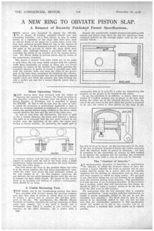
TrinE piston ring described in patent No. 300,422, _L W. S. Bauer, of London, contains several new and interesting features. At -a first glance, it may he taken merely as a repetition of the rings that have been used on certain kinds of -air .pump for a great many years. and have been patented several times for use in the engines. of motor vehicles. In the instances referred to above, however, the sides of the groaves in which the rings fittedwere parallel; this, although forming a gas-tight seal,• did not centralize the piston in its cylinder as in the present invens Lion. Mr. Bauer claims to prevent piston slap by means of the construction described.
The groove is formed with sides which are at an angle to each other, the two rings which contact with the cylinder walls lavespractieally nospring in them, but are forced outwards by means. of. the central ring, which provides the necessary amount of spring to ensure a gas-tight seal, both with the cylinder-walls and with the sides .of the groove and, at the same time, centralizes the piston in the cylinder. The specification recommends two sets of such rings, spaced equally aboVe and below the gudgeon pin, thus farming not only a perfect gas seal but a means whereby piston slap is prevented.
Silent Operating Valves, mANY devices have been inVented with the object Of " silencing the operation of valves ; the latest invention in this direction, however, emanates from the fertile brain of Ettore Bugatti, of Molsheim, and is described in patent o.-' 270,700. In this it will be seen that the class of 'valve to which the invention is particularly applicable is that in which an overheadcamshaft is employed to operate inverted valves, the special feature being confined to the levers which operate between the cam and the end of the valve stem.
As will be seen from the illustration, the lever is split up for a certain distance, the lower part forming a spring, The split is so arranged that the two parts contact at the portion near the beginning of the split, the upper part halting a curved surface. In operation,. the upper part is 'n constant contact with the cain, whilst the lower part is always in contact with the end of the valve stem, a slight compression being necessary to introduce the lever between the cam and valve stem.
One view shows the lever in the position where the valve is in the closed position, the fork being approximately open, whilst the other view shows the fork gradually closing as the cam presses on it. , As this pressure continues, the gap between the two parts becomes shorter until the two are in contact for their whole length. By means of this device there is no breaking and making of contact; consequently, there should be no noise.
A Useful Recessing Tool.
THIS simple tool is for transforming pistons that have
been provided with inferior means for securing gudgeon pins into that class of piston in which there is a groove to receive a spring ring to prevent the end-wise movement of the pin. The specification, No. 300,159, Hector Turnbull, of London, deseribeS the tool asconsisting of three parts only, namely,' (1) a key with, a handle and a rectangular stem which is parallel in one condition. hut tapering' in the Other direction, (2) a cutter with a
c48
Despite the considerable number of inventions dealing with pistons and piston rings there are but few deviations front standard practice in the average engine used in the commercial vehicle.
rectangular hole in it and, (3) a collar for determining the position of the groove to be formed in the piston.
In use the operation is as follows. A sleeve, which may consist of a hollow gudgeon pin, is placed in the hole, first having the collar set at the required distance so that the • end of the pin comes to the part where the groove is required to be cut ; the cutter is then placed on the stem of the
key and revolved by hand. As the tapering part of the stem of the key is pressed inwards it forces the cutter outwards until the required depth of groove is obtained. All that is necessary in the converting of pistons by this method is to shorten the gudgeon pin by grinding the unwanted metal off the ends untila ring of wire can be inserted.
Tbe "Control of Gravity."
AN epoch-marking invention is described in specification
No. 300,811, in which the inventor claims to have discovered a means whereby the force of gravity can be controlled, thereby giving us a power that can be usefully employed for the driving of automobiles and, in fact, any and every purpose to which: we apply power. We are glad ta say that these claims are not put forward by an Englishman, the inventor hailing_ from America. The specification is a long one and, to us, is. incomprehensible. If the inventor • has a working model that will demonstrate his claims we should be glad to make a journey across to be the first to bring the glad news to this country..
We understand that the law demandS that a complete patent specification "must contain sufficient information to enable a person reasonably skilled in the 'art to put the invention into practice." We think that we may be considered to he reasonably skilled in this art, but we feel sure that the information contained in this specification would not enable us to pat it intopractice uml by so doing produce' a machine that would enable us to control gravity.