


MOUNTING THE BUS BODY.
Page 21
Page 22
Page 23
If you've noticed an error in this article please click here to report it so we can fix it.
The Main Dimensions Required by the Co'achbuilder. The Construction of Wings and the Arrangement of the Steps.
T HE motor manufacturer supplies the bodybuilder _L with a dimensioned drawing of the chassis, so that the body may be designed before the delivery of the chassis. In some instances the construction of the body may be well advanced before the arrival of the chassis, therefore it is important that the chassis print shall not only be accurate, but give full Information. The bus proprietor should also have some knowledge of the chassis measurements required by the bodybuilder, because, occasionally, he may want a new body mounted on a chassis which is being overhauled and he wishes to supply the requisite data in order that the bodybuilder may prepare a drawing and estimate.
The principal dimensions which are concerned with the mounting of the body are as follow :—(1) The wheelbase, that is the distance apart of the front and hind axles. If a chassis he measured care should be taken to see that the front wheels are not on lock. For dimensions over 6 ft. it ensures greater accuracy if a long wooden rod or straightedge can be used. The most important part of the wheelbase is that portion of it from the dash to the centre of thehind wheel, as this decides the Position of the wheelarch, which, in turn, controls, to a certain extent, the seating plan.
.(2) The wheel track, which is usually expressed as the distance apart of the tread centres of the wheels on the same axle. With twin wheels this centre will he between the two tyres. The bodybuilder, however, is chiefly concerned with the distance apart of the inner faces of the hind wheels, the overall width of the tyres and the overall width of the axle caps. Then he can estimate the amount the wheelarch will project inside the body and the width of wing required to form an effective mudguard. , (3) The actual wheel diameter is important, as it may be confused with the reputed tyre size. Closely connected with the wheel diameter is the amount of clearance above the hind wheel required for the deflection of the springs. This is usually expressed as a vertical dimension above the top of the chassis, or as a radius for the outline of the wing.
(4) The body space of the frame, that is its overall length and width behind the dash. Its loaded height above the ground should also be given, as this dimension influences the height of the wheelareh and the setting out of the steps. The bodybuilder should also know the position and size of all chassis crossbars, the location of ill inspection traps, lubrication centres likely to be covered by the body structure, also the position of the fuel tank and its filler.
(5) The position of the steering wheel must be given, so that the driving seat may be placed in its proper position. This seat, in turn, decides the position of the front bulkhead and, therefore, the space available for passenger seats. When side control levers are fitted the side framework of the body has to be designed so that there is room for their operation.
(6) In modern bus design the height and width of the bonnet, both at the radiator and dash, is important if a flush-sided scuttle dash is to be built.
(7) The overall length of the chassis from the front spring shackle, or starting handle, whichever is the most forward part of the chassis, to the extreme end of the chassis must be known. From this dimension the bodybuilder can then calculate where the limit lies of the 7-24ths overhang.
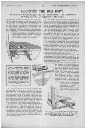
The main framework of the body is put together on low trestles, or a special platform. The joints of the bottom framework are then easier of access than if the body were mounted on the chassis. ViThile the body is close to the ground the opportunity is usually taken to board or panel the roof also. The body, however, is mounted as soon as possible, because it is then more easily shifted for its progress through the shops. Early mounting saves much time, because any minor adjustments necessary in order that the body shall fit the chassis accurately can be made before the panelling is completed or the floorboards laid.
The typical bus body is about 7 ft. wide at the waist and 6 ft. 6 ins, across the bottom. The width of the chassis seldom exceeds 3 ft. 6 ins., therefore the overhang of the body on each side is about 1 ft. 6 ins. As this overhang represents approximately half the width of the crosswise seats and tile Whole of the longitudinal seats it will be seen that -a Iarge-proportion of the passenger load has to be supported outside -the normal width of the chassis.
Even when the bus is only partially filled the passengers will generally .select the innef`and more comfortable seats. In order to support this comparatively large overhang some chassis are provided with outrigger mounting brackets, which form, in effect, a continuation of the cross-members of the chassis. These brackets allow the bottom framework of the body to be made lighter; they can be used to introduce new methods of constructing the bottom framework, whilst they can also he employed to improve the mounting of the body by the introduction of a robber pad, or other resilient device, at a position where it will be most effective.
Although coiled springs are muea used for the main. or supplementary suspension of rail vehicle bogies, they de not appear to be much in favour for road vehicles, except for shock absorbers. The coiled spring has the advantage that it takes up little rociin and one spring may be inserted inside another. By this means a lighter and inner spring can take care of the minor shocks which are not fully absorbed by the chassis -springs, whilst an outer and stronger spring takes up its load when road conditions are particularly severe.
It is suggested that a nest of coiled•springs could be mounted on the end of a specialty designed outrigger bracket. This form of mounting should be particularly valuable on any crossbars beyond the hind axle centre.
The body should be fastened to the side members of the chassis by means of clips and not bolls. These clips, as they embrace a crossbar placed at right anglesto the chassis, must be fixed at an angle of 45 degrees. The top arch of the clip bears on a Metal stirrup and is bedded on a piece of leather. The clip is fastened by means of a coupling and a pair of nuts. If' the body be bolted down both the chassis and the crossbars have to be drilled and these holes must be registered when the body is remounted.
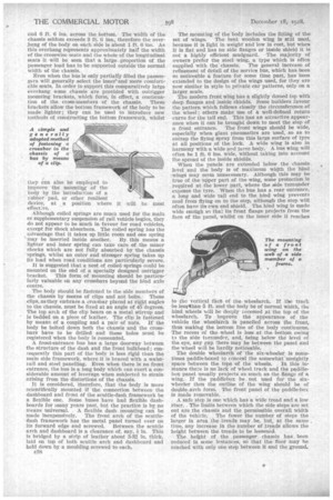
A front-entrance bus has a large doorway between the structure of the dash and the front bulkhead; coneequentIy this part of the body is less rigid than the main side framework, where it is braced with a waistrail and steel panelling. Even when there is no front entrance, the bus is a long body which can exert a considerable amount of leverage when subjected to strain arising from the distortions of the chassis.
It is considered, therefore, that the body is more scientifically mounted if the connection between the dashboard and front of the scuttle-dash framework be a flexible one. Some buses have had flexible dashboards for many years past, but the practice is by no means universal. A flexible dash mounting can be made inexpensively. The front arch of the scuttledash framework has the metal panel turned over on its forward edge and screwed. Between the scuttle arch and dashboard is a clearance of, say, + in. This is bridged by a strip of leather about 3-32 in. thick, laid on top of both scuttle arch and dashboard and held down by a moulding screwed to each.
038 The mounting of the body includes the fitting of the set of wings. The bent woOden wing is still used, because it is light in weight and low in cost, but when it is flat and has no side flanges or inside shield it is not a highly efficient mudguard. The majority of owners prefer the steel wing, a type which is often
supplied with the 'chassis. The general increase of refinement of detail of the service bus, which has been SO noticeable a feature for some time past, has been extended to the design of the wings used, for they are now similar in style to private car patterns, only on a larger scale.
The modern front wing has a slightly domed top with deep flanges and inside shields. Some builders favour i he pattern which follows closely the circumference. of the wheel; others make use of a well-defined return curve for the tail end. This has an attractive appearance when it can be brought down to meet the step of a front entrance. The front wings should be wide, especially when giant pneumatics are used, so as to entrap the Eying spray from this large surface of tyre at all positions of the lock. A wide wing Is also in harmony with a 'wide and large body. A. bus wing will often be ft. 6 ins, wide, without taking into account the spread of the inside shields. When the panels are extended below the chassis level and the body is of maximum width the hind wings may seem unnecessary. Although this may be true of the upper part of the wing, some protection is required at the lower part, where the side turnunder exposes the tyre. When the bus has a rear entrance, a long and wide tail end to the hind wing prevents mud from flying on to the step, although the step wilt often have its own end shield. The hind wing is made wide enotigh so that its front flange projects from the face of the panel, whilst on the inner side it reaches to the vertical face of thewheelarch. If thbo track be lessithan 5 ft. and the body be of normal width, the hind wheels will be deeply recessed at the top of the wheelarch: To , improve the •appearance of j the vehicle the wheelarch is panelled across the front, thus making the bottom line of the body continuous. The recess of the ,wheel is less at the bottom • owing ta the side tornunder, and, being below the level of the eye, any gap there may be between the panel and the wheel will be hardly notieeable. .
The double wheelarehof -the six-wheeler is sometimes paddle-boxed to 'conceal the scanewhat'unsightly space between the "toPS'of• the wheels. . In thin :instance there is no lack of wheel track and the paddlebox panel, usually projects as, much as the flange of a wing. If the paddlebox be not used for the Sixwheeler then the outline of the wing should be of dotiblecareh form. • The front panel of the paddle-box
is inade removable. . . .
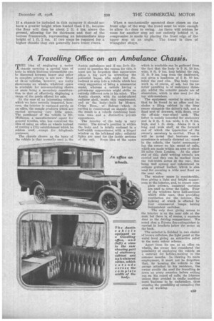
. A safe step is one which has a wide tread and, a low riser. . The limits between which the side steps are 'set out are ..the chassis and tlie permissible overall width Of the vehicle. The fewer the 'number of steps the larger in area ,the,:treads may , be, but,' at the same time, any increase. in the number of „treads allows the height between the treads to be lessened. •
The heWat of the .passenger,. chassis has,, been reduced in some instances, So that the fiber may be reached with. onIST one step between it and the ground.. If a chassis be included in this category it should not have a greater height when loaded than 2 ft., because the floor will then be about 2 ft. 4 ins, above the ground, allowing for its thickness and that of the bottom framework, representing an intermediate step height of 1 ft. 2 ins. If two steps be required for a higher chassis they can generally have lower risers.
When a mechanically operated door closes on the front edge of the step the tread must be wide enough to allow th. door to swing. As there will seldom be room for another step set out entirely behind it, a compromise is made by placing the front edge of the upper step at an angle. The tread is then of triangular share.