


ASSEMBLING A MOTOR COACH WIRELESS SET.
Page 13
Page 14
If you've noticed an error in this article please click here to report it so we can fix it.
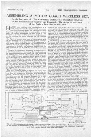
In the last issue of "The Commercial Motor," the Theoretical Diagram of the Recommended Receiver was Discussed. The Actual Arrangement of the Parts is Described in this Issue.
HAXING now outlined the requirements of a good radio receiver for motor coach work and described in some detail the theoretical wiring diagram we propose, in this present article, to consider the actual disposition of the parts of the receiver as a whole and to give some indication as to the reasons for their disposal in the manner shown.
In Fig. 3 is given a plan view of the receiver with the box removed, so as to show the interior arrangement. It will be seen that the whole apparatus is built up on a wooden base which has an ebonite front attached to it at right angles. This makes an arrangement of L-shape_, the ebonite forming the upright portion of the L and the wood the horizontal part.
This plan of instrument mounting is far preferable to the usual method of mounting the components on the underside of the ebonite panel and then mounting the lot in a box, since it allows of the whole interior being withdrawn and standing erect when so withdrawn without any further' support. This is invaluable when wiring up the receiver, and it. is also very useful should, at. any future date, a fault develop in any particular part. Owing to its design, the whole interior, when withdrawn, forms the entire set and can, if need be (for locating a fault as mentioned above, for instance), be worked on the aerial. The box in this set is merely a case or cover into which slips the receiver proper. The next thing to notice is that all the valves are inside the case, so that, when the receiver is in its box, they are absolutely protected from accidental damage. Further reference to Fig. 3 will show that the valves are not all mounted together, as is the usual practice, but are in two groups of two each. The reason for this is that it allows of very much shorter internal wiring in the 'receiver, and this, as has been pointed out in an article in the previous series, is conducive to efficiency, since the capacity, or condenser effect, between long and closely juxtaposed leads is a. very frequent source of considerable loss in signal strength and also one of the most fruitful causes of instability, especially where use is made of high-frequency amplification (as is done in the case of the set we are describing). Two short strips of ebonite are used to carry the valve sockets and ensure good insulation betaeen grids and plates of the various valves—an important precaution if a silent-working receiver is to result. These ebonite strips are mounted on small battens at each end, so as to leave a space of about 14 ins. between the underside of the ebonite and the top of the baseboard.
The strip at the back of the set carries the highfrequency and detector valves, that in front and to the right the two-note magnifying valves. Between the high-frequency and detector valves is situated the coupling condenser, which is of the fixed pattern and should have a value of .0003 micro-farads. This position is again chosen with a view to reducing the wiring to the absolute minimum. and, in this connection, it will be noted that the grid leak, the function of which is to keep down the excessive negative charge on the grid side of the coupling condenser, is inserted right between the valve leg and the condenser, without any extraneous wiring whatever. The leak is shown connected to the positive end of the detector filament, and this will generally be found to be necessary in order to render the set stable, although in a few valves better results are obtained by connecting the grid leak to the negative side of the detector filament. The exact connection depends upon several variables, such as the shape of the characteristic curve of the valve, the filament brilliancy of the plate potential, also the value of the grid leak, but, generally speaking, ethe connection shown is correct. The leak should have a mean value of 2 megohms or two million ohms.
On the extreme left of the case is the viriometer that we have chosen as a means of tuning the aerial. In the next article we propose to deal with the question of variometers in detail, so we shall not say more here about the subject beyond pointing out that the position of the variometer is such that the only internal wiring in the aerial circuit is that between the aerial and earth terminals and the variometer itself—not more than four inches.
Next to the variometer will be found the seven.plate variable fair condenser, which, in conjunction with the anode coil alongside it, 'forms the tuned plate circuit. Here again the arrangement is as compact as it can be made. Coupled to the plate coil is the reaction coil, which is so mounted that it can partially rotate in the direction shown, so that the coupling can be varied. This rotation is controlled by means of a slow-motion device, since it is essential for efficiency that the coupling be as critical as possible ; in other words, that the variation between them be as delicate as it can be made.
The position of the two low-frequency transformers
is such that there is no possibility of their interacting and causing howling. They are well separated and turned at right angles to one another. The core of the telephone transformer is also at right angles •to that of the nearest transformer. Between the two intervalve transformers is situated the grid battery, the function of which is to bias the grids of the noteamplifying valves. As will be seen, the whole receiver is of such a shape and of such dimensions that it can be accommodated in only a small coach, with little room to spare in front of the dashboard.