A DEVICE TO ASSIST GEAR-CHANGING.
Page 28

If you've noticed an error in this article please click here to report it so we can fix it.
A Resume of Recently Published Patent Specifications.
THE invention, which is described in specification No. 235,509, by F. A. Hayes, of America, is merely intended as an adjunct to the ordinary design of sliding gearbox. Its.object late render if impossible to slide gears into mesh. until their peripheral speeds are equal. The specification is necessarily a long and somewhat complicated one, so it will only be possible here to outline the principle of the invention.
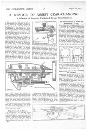
The short shaft shown on the right in the accompanying drawing is connected to the engine in the usual manner. A layshaft is provided and sliding gears, more or less of the standard type, are used, these being operated by the ordinary selector rods. A disc will be seen on the left of the driven shaft, whilst on the left end of a shaft geared to the
layshaft is a similar disc. A spring pressure between these discs causes then/ to grip the roller shown between them. This roller is free to revolve, and also to slide, on its shaft. This shaft does not lie in a truly redid line between the centres of the two discs, so that when gripped between the discs the roller will travel the entire length of its shaft. Attached to the boss of this roller is a finger which engages the selectors in such a manner that they can only slide and bring about an engagement of the gears when the roller is in a certain predetermined position—that position indicating the point where the peripheral speeds of the two gears to be engaged are equal.
The specification refers to the arrangement as "a synchronizer," and points Out that it will only permit of the engagement of gears the pitch-line velocities of which are equal.
Improvements in Lamps.
IN specification No. 236,394, Tale Wiremu Ratana, a native of New Zealand, describeS an improved 'system of lighting. As will be seen from the illustration which we publish, the lamp is of the duplicate type ; that is to say, it has two bulbs, one showing a light for 844 ward and the other showing a light at an angle towards the rear. A switch is shown which operates the headlamps as well as the smaller double lamp. When the switch (A) is in the position shown the headlamp is cut off, but when in con tact with the headlamp only is on. The object of the idea is to illuminate the roadway behind the vehicle, and by so doing to enable a vehicle passing in an opposite direction to see the road.
A somewhat similar idea was recently referred to in another specification, in which the lamp which threw a light to the rear was mounted on the rear mudguard. This would seem to be a better position for it, as it would not be visible to and possibly affect the sight of the driver to whose vehicle it is fitted.
An Improvement in Rims for Pneumatic Tyres.
RUDGE-WHITWORTH, LTD., J. V. Pugh and G. H. Vernon describe, in specification No. 236,610, an improved construction of rim for pneumatic tyres, in which a central abutment is provided, as shown in both views in the illustration which we reproduce. This central abutment forms two channels in which the edges of the tyre are gripped. The flanges may eitherbe made detachablet on one side, as shown in the left-hand ,view, or with both flanges detachable, as shown in the other view. In the case of the former, the central abutment is removed to enable the tyre to be taken off the rim, whilst in the right
Improvements in the Steering of Trailers.
PATENT No. 235,692, by H. .Newport, describes a form of trailer in which the steering is effected by means of stub axles and 'connections on the Ackerman lines. By this means the central pivot is dispensed with, the wheels steering as in an ordinary vehicle.
Another feature of the invention is the arrangement of the brake, which is .so designed that it automatically applies itself if the trailer through any cause becomes detached from the tractor. The pull-bar is necessarily of some considerable weight and is only held up 'by its connection to the tractor. Should this connection fail, the pull-bar drops, as shown by the dotted lines in the drawing reproduced herewith. The pull-bar, having a second bar hinged under the main hinge, causes the link (A) to reverse its angle as shown at Al and, by so doing, to apply the -brake by tightening the cable.


