


Simplified Injection Pump
Page 50
If you've noticed an error in this article please click here to report it so we can fix it.
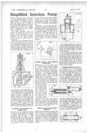
THE conventional type of injection pump varies its. output by the wellknown method of rotating a helically edged plunger. An injection pump its which the output can be varied by much more simple mechanism is shown in patent No. 667,564, by the AngloIranian Oil Co., Ltd., and J. Shaw, both of Britannic House, Finsbury Circus, London, E.C.2.
The pump described varies its delivery by altering the stroke of the plunger, but the geometry of the motion is such that injection always commences at the same moment, whether a large or small delivery is being made.
Referring to the drawing, the' plain plunger (1) uncovers an inlet port (2) at the bottom of the stroke, this position always being reached whatever the length of stroke. The driving shaft (3) earths an eccentric which reciprocates a connecting-rod (4) carrying a roller (5) on its small end. Pivoted also on the roller pin is a short ball-ended connecting-rod (6) which works the tappet.
The roller rides on a cam-track (7) which is pivoted on trunnions in the casing, in such a position that at bottom stroke both roller' and trunnions are co-axial. The cam-rack can be rocked by an eccentric shaft (8) the position of which gives the output control. The length of the stroke, and consequently the quantity of fuel pumped, depends upon the distance the roller travels up the slope of the cam.
STARTING OIL 'ENGINES ON LIGHT FUEL
IN some types of compression-ignition
engine it is the practice to arrange an electric heater-coil in the intake manifold, and to inject a small quantity of light fuel, such as petrol, for example, on to the heated coil by means of a hand-pump. The object is, of course, to facilitate starting. Patent No. 666,997 shows an automatic A40 injector which supplies a fixed quantity of petrol, and so prevents excessive priming such as might occur with a mis-handled hand-pump. The patentee is C.A.V., Ltd., Warple Way, London, W.3.
Referring to the drawing, the lightfuel tank (l) is piped to the intake via a solenoid-operated single-stroke pump (2). This unit, when energized, delivers a measured quantity of fuel to the injector (3). The intake heater-coil (4) is wired in the same circuit as the solenoid pump, so that the single act of switching-on is all that is necessary, and no reliance is placed on human judgment.
RUBBER SPRING FOR VEHICLE SUSPENSION ATENT No. 663,195 comes from
R. Seddon and the Dunlop Rubber Co. Ltd., 1, Albany Street, London, N.1iV.1, and it covers a design for a rubber spring suitable for road-vehicle suspension. The scheme iS illustrated as applied to an independent system employing parallel links, and the drawing shows the layout as it would appear under its static load.
In the drawing (1) is the lower of a pair of swinging arms connected by a link shown partly at (2). The pivot (3) is fixed to the chassis, and the arm oscillates about this point to the extent shown by the broken lines. The spring consists of five rubber collars (4) cemented together and housed in a tube (5) which may form part of the vehicle frame.
The central rod is attached to the arm at (6), and its deflections react against the compression of the rubber. The response rate can be adjusted by removing an inspection cover (7) and screwing the rod into or out of the nut (8).
FORCED AIR-COOLING FOR PISTONS
(\NE of the problems connected with
the desrgn of two-stroke engines is that of adequately cooling the piston, and a novel means for doing it is shown in patent No. 666,032 by T. Logaslikin, Queensland, Australia. Although more necessary for two-stroke engines, the scheme may also be applied to four. strokes.
The drawing shows one cylinder of a multi-cyliridered two-stroke oil engine. Passages pass transversely through the piston. A charging blower (1) supplies low-pressure air to a gallery (2) serving all the cylinders.
As the piston approaches top dead centre, the passages in the piston line up with air ports in the wall, and a cooling blast passes right through the piston and charges a closed chamber (3) on the opposite side. The air remains in this chamber until the succeeding bottom stroke, when it escapes over the piston crown to form part of the main charge in the cylinder.
ARUBBER-BUSHED SHACKLE
ADESIGN for a rubber-bushed shackle, said to be particularly suitable for the heavier types of vehicle, is shown in patent No. 667,172, by H. Clayton-Wright, "Wellesbourne House," Welles bou rag, Warwickshire.
In the drawing, 1 is the spring eye, 2 the shackle links and 3 the pin. The pin has ends of reduced-diameter and each receives a pair of rubber bushes (4). The hushes are made longer than
the space available for them. so that when the end washers are pulled up to their shoulders, the rubber is squeezed out into flanges (5) which separate the two components. The rubber, when compressed in this manner, acts as a fluid and firmly grips the central pin, so that all deflections are accommodated by torsion in the rubber.