


A Torsion-bar Suspension Layout
Page 54
If you've noticed an error in this article please click here to report it so we can fix it.
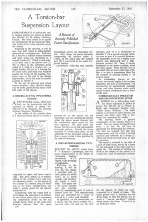
IMPROVEMENTS in torsion-bar sus" pension systems are shown in patent No. 602,065, by M. Julian, Toulouse, France. The main object is to peintit the employment of the maximum effective length of bar when mounted across the chassis.'
Referring to the drawing, it will be seen that each wheel is independently mounted on a swinging arm. Each arm (1) is fixed to a tubular torsion member and both tubes are journalled in a central bracket (2). Fixed to each tube, at its inner end, is an interior rod (3); thi is taken to the outermost point where it is held in a bracket (4). A larger bracket (5) acts as a bearing for the outer tube, and these two brackets receive the brunt of the loading, but, being close to the end of the chassis side-member, are in the most favourable position to receive it.
Ry the use of outward and return torsiciL-members, their effective length can be made approximately equal to the full wiath of the chassis.
A DOUBLE-ACTING TWO-STROKE ENGINE
ATWO-STROKE engine, which fires both on the downstroke and the upstroke, is shown in patent No. 602,310, by R. Wigmore, 41, Chartley Avenue, Stanmore, Middlesex.
In the middle of .the cylinder there is a short stationary piston (I) which is
supported by upper and lower central Pith. The main piston (2) is hollow, sliding in the cylinder bore, and over the stationary piston. At the bottom of the cylinder is a clesure plug (3) which acts as the lower cylinder-head, and holds a sealing gland for the tubular piston-rod (4).
Considering only the upper half of the cylinder, the operation is as follows: As the hollow piston rises, it commences the compression stroke On the top cylinder-head, while at the same time drawing mixture into the space A36
immediately above the stationary piston. After firing, the piston descends, compressing the mixture under it, whilst, on the upperside, the exhaust port (5) is uncovered in the usual twostroke fashion.
Immediately following this, transfer grooves (6) on the central rod are uncovered, and the compressed mixture under the piston passes through into the combustion space ready for the next upstroke. No inlet ports are shown, but they are of the conventional two-stroke pattern. Exactly the above sequence of events takes place on the underside of the stationary piston, and thus a power stroke is also provided in the upward direction.
A SELF-SUPERCHARGING TWO' STROKE
PATENT No. 602,137 comes from P. Knutzen, Copenhagen, and discloses improvements in the design of two-stroke engines,
particularly with regard to the pumping arrangements.
Referring to the drawing, it will be seen that the engine is provided with an extra piston (1) which works in a lower cylinder and incidentally forms a crosshead. The upper one is the power cylinder and has scavenge
ports (2), supercharge ports (3) and an exhaust valve (4). The supercharging ports are controlled by a valve (5) worked by a rocker and camshaft.
In operation, on the downstroke, air is drawn into the lower cylinder via a one-way valve (6) and on the next
upstroke, part of it is transferred to chamber 7 via a second one-way valve. As soon as port 8 is covered, however, the remainder of the air is highly compressed and discharged into a highpressure receiver (9). Here, it awaits admission to the power cylinder, when the valve opens. Note that the cam is provided with an extra small lobe (10); this is to give a momentary blast for the purpose of clearing pocket 11 of exhaust gases.
An outstanding feature of the normal two-stroke engine is its extreme simplicity, and ease of construction. The introduction of mechanically operated valves and other fitments could easily render it more complicated than a fourstroke unit.
HYDRAULICALLY OPERATED
REFUSE-COLLECTING SCOOP A DESIGN for a self-loading body in for refuse collection is shownin patent No. 602,107, by L. Watts, P. Hugh and Scammell Lorries, Ltd., Tolpits Lane, Watford. The main scheme is covered by other patents; the present one deals only with a new means for operating the loader.
The drawing shows a general arrangement of the scheme fitted to a trailer. The rear section 'is hinged about. point 1 so that the end 'can be uncovered for discharging the contents. The bins are emptied into this rear compartment, and the refuse is carried upwards and forwards by a scoop (2) which can travel forward as far as may be necessary.
The scoop is attached to one side of a pair of cable loops, driven by a drum (3) and tensioned at the other end by a pulley (4). The method of driving the drum is the subject of the patent; it is worked by a pair of hydraulic cylinders (5), the pistons of which are interconnected by a length of chain. The chain passes over a sprocket on the drum shaft, so that the pistons can be given a "one-up one-down" motion which rotates the drum. Control is by an hydraulic valve.