


ANOTHER SWASH-PLATE ENGINE.
Page 32
If you've noticed an error in this article please click here to report it so we can fix it.
A Résumé of Recently Published Patents.
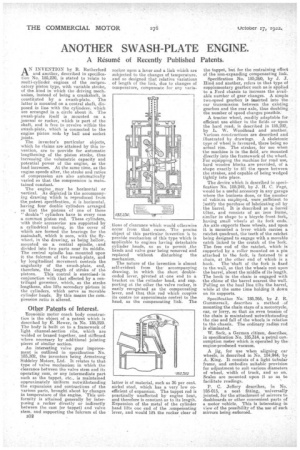
AN INVENTION by R. Rutherford and another, described in specification No. 185,230, is stated to relate to multi-cylinder engines of the reciprocatory piston type, with variable stroke, of the kind in which the driving mechanism, instead of being a crankshaft, is constituted by a swash-plate. , The latter is mounted on a central shaft, disposed in line with the cylinders, which are arranged in a circle about it. The awash-plate itself is mounted on a journal or rocker, which is part of the shaft, and. is free to revolve within the awash-plate, which is connected to the engine piston rods by ball and socket joints.
The inventor's particular objects, which he claims are attained by this invention, are to provide for -automatic lengthening of the piston stroke, thus increasing the volumetric capacity and potential power of the engine, as the load increases. At the same time, as the engine speeds-alter, the stroke and ratios of compression are also automatically varied so that the compression is maintained constant.
The engine may be horizontal or vertical. As depicted in the accompanying . drawing which is reproduced from the patent specificatime it is horizontal, having four double 'cylinders arranged so that. the pistons of one of these " double ". cylinders have in every case a commoi piston rod. -These cylinders, with their accessories are supported by a cylindrical casing, in the cover of which are formed the bearings for the mainshaft, which is seen, with the flywheel, in the drawing, as being hollow, mountedon a central spindle, sand divided into two parts near its middle. The central spindlehas. mounted upon it the fulcrum of the swash-plate, and by longitudinal movement controls the angularity of the • awash-plate, and, therefore, the length of stroke of the
pistons. This control is exercisedin conjunction with that effected by a centrifugal governor, which, as the stroke lengthens, also lifts secondary pistons in the cylinders, which serve as movable cylinder heads. By this means the compression ratio is altered.
Ogler „Patents of Interest.
Economic motor coach body construction is the object of a patent Which is described by E. Hewer, in No. 185,229. The body is built on to a framework of light channel-section ribi, which are welded or brazed together, and stiffened where necessary by additional jointing pieces of similar section.
An interesting valve gear improvement is outlined in specification No. 185,302, the inventors being Armstrong Sicldeley Motors, Ltd. It relates to that type of valve mechanism in which the clearance between the valve stem and its operating cam, or any intermediate part such as the tappet, etc., is maintained approximately uniform notwithstanding the expansions and contractions of the various parts, brought about by changes in temperature of the engine. This uniformity is attained generally by interposing a rocker directly or indirectly between the cam (or tappet) and valve stem, arid supporting the fulcrum of the 1532 rocker upon a lever and a liuk which are subjected to the changes of temperature, and so designed that relative variations of length of the link, due to changes of temperature, compensate for any varia Lions of clearance which would otherwise occur from that cause. The precise object of this particular invention is to provide mechanism of this type which is applicable to engines having detachable cylinder heads, so as to permit _the heads and valve gear being removed and replaced without disturbing the mechanism.
The nature of the invention is almost. self-evident from the accompanying drawing, in which the short doubleended lever, pivoted at • one end to a bracket on the cylinder head, and supporting at the other the valve rocker, is easily recognized as the compensating • lever, and that thin rod which couples its centre (or approximate centre) to the head, as the compensating link. The latter is of material, such as 36 per cent. nickel steel, which has a very low coefficient of expansion. The tappet rod is practically unaffected by engine beat, and therefore is constant as to its length. Expansion of the metal of the cylinder head lifts one end of the aompensating lever, and would lift the rocker clear of the tappet, but for the restraining effect of the non-expanding compensating link.
Specification No. 185,260, by JHind and another, refers to that type of supplementary gearbox such as.ia applied to a Ford chassis to increase the available number of gear changes. A simple two-speed gearbox is in.serted into the car transmission between the existing gearbox and the rear axle, thus doubling the number of speed changes possible.
A tractor wheel, readily adaptable for efficient use either in the fields or upon the hard road, is described in 185,292, by L. W. Woodhead and another. Various constructions are described and
illustrated by drawings. A skeletonic type of wheel is favoured, there being no actual rim. The strakes, for Use when the machine is in the field, are mounted directly into the framework of the wheel For equipping the machine for road use, hard wooden blocks are provided, of a shape exactly to till the space between the strakes, and capable of being wedged tightly into place.
The device which is described in specification No. 185,249, by J. II. C. Page, would be a useful accessory in any garage where the business done, or the number of vehicles employed, were sufficient to justify the purchase of lubricating oil by the barrel. It is described as a barrel tilter, and consists of an iron frame, similar in shape to a bicycle front fork, having small wheels at its fork ends. An axle supports these wheels, and upon it is mounted a lever which carries a ratchet quadrant, theleeth of the ratchet being designed to engage with a movable catch linked to the crutch of the -fork. The free end of the ratchet, which is supported by a roller mounted on a pin attached to the fork, is fastened to a chain, at the other end of which is a hook. The 'shaft of the fork is fixed to the wall, so that the wheels rest upon the barrel, about the middle of its length. The hook in the chain is engaged with the chime of the barrel nearest the wall. Pulling on the haul line tilts the barrel, while at the same time holding it down on its supports.
Specification No: 185,266, by S. R. Gemmersall, describes a method • of mounting the chain stays of a motorcycle, car, or lorry, so that an .even tension of the chain is maintained notwithstanding the rise and fall of the wheels in relation to the chassis. The ordinary radius rod is eliminated.
W. Seek, a German citizen, describes, in specification No. 185,314, a petrol consumption meter which is operated by the engine-produced vacuum,
A jig, for use when aligning car wheels, is .described in No. 184,944, by A. King. It consists of a light tubular frame, and embodies suitable provision for adjustment to suit various diameters of wheel, width of track, and so on. Scales are mounted upon it so as to facilitate readings.
P. C. Jeffery describes, in No. 185-015, a neat fitting, nniversally jointed, for the attachment of mirrors to dashboards or other convenient parts of a motor vehicle, This is interesting in view of the possibility of the use of such mirrors being enforced.