


HINTS ON MAINTENANCE.
Page 30
Page 31
If you've noticed an error in this article please click here to report it so we can fix it.
How to Get the Best Out of a Vehicle, to Secure Reliability and to Avoid Trouble.
CONTRIBUTIONS are invited for this page from fleet managers, drivers, garage foremen, and mechanics, works staff and draughtsmen, and will be paid for on.a generous scale. Every system, make, and type of commercial motor vehicle will be dealt with, and the matter should be written with a view to the disclosure of workshop and garage practice in the maintenance of a vehicle—practices which, whilst they may be quite normal, are peculiar to the particular vehicle and may not be generally known to those responsible for its running. Expedients and suggestions for overcoming roadside and other troubles are covered in the following page, dealing with letters from our driver and mechanic readers. Communications should be addressed to " The Editor, The Commercial Motor, 7-15, Rosebery Avenue, London, E.C.1."
277.—Securing Wheel Nut on Thornycroft—A Correction.
We have received from ,Tohn I. Thornycroft and Co., Ltd., the following useful advice on the subject of the locking device used for the rear wheels of their J-type vehicle:—
"On page 210 of your issue of October 3rd, under the heading Hints on Maintenance,' your Hint No. 273 on securing a wheel nut on the, Thornycroft has come to our notice, and the suggestion made by your contributor is not one which we can endorse.
" We would point out that at all times the securing nut must be driven firmly home against the washer, which, in its turn, must be hard up on the axle sleeve. This condition cannot be ensured when screws are fitted in the manner suggested, and it is probably because the need for this condition is not perfectly understood that trouble has occurred with the threads stripping.
." It is clear that, unless the washer and nut are firmly home, any end chatter of the wheel will, cause. movement to take .place between the nut and the thread on the sleeve, with consequent wear on both of these parts. On the other hand, if the nut and washer aye firmly home, no such movement can take place.
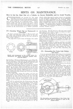
"It will he noticed from the illustrations that the washer is provided with seven tapped holes, whilst the nut has six slots. This differential, or Vernier, locking arrangement is provided expressly to allow for the firm adjustment to which we refer above.
" Referring to the diagrams, if it be assumed that the washer and nut have been removed for the purpose of taking up the end-play of the wheel by means of the fibre washers which we supply for the purpose, when the nut and washer are reassembled it is very probable that the nut will not be sufficiently tight when the same pair of slots which previously contained the locking screw come together. If that he so, the nut should be further tightened so that the slot in the nut next to the one previously occupied by the screw,. working round in an anti-clockwise direction, is forced round to coincide, with the tapped hole in the washer by the amount shown at A, on
B30 our. drawing. Should, however, this slot come round into position too easily, it may be better to insert the locking screw even at B.'
It will be noted from the drawing what a very small amount of movement is necessary to bring the next adjustment slat and bole to coincide for insertion of the screw, the amount being actually 8i degrees, so that, in effect, it is possible to insert the locking screw in 42 different positions round the CCITApiete circle of rotation. "The large number of locking positions provided by this method should surely obviate the necessity for assembling these parts with any slackness, and we know from experience that if no slackness is allowed: to be present when assembling the parts, none will develop in use, and that, therefore, the nuts will not strip."
278.—Dismantling the Foden Link Motion and Gears.
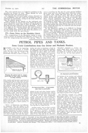
It is not generally known that when it is necessary to release the link motion on the Foden wagon in order to perform repairs to the H.P. and L.P. slide valves; a very simple method can be used for achieving.this object. The pins which are marked 1 and 2 on the diagram, should be knocked out, and the link motion is then free to rest on the gauge plate, so that the valve spindles can be withdrawn, .
It is advisable to hold a piece of wood at the off side of the pins when knocking them out.
The slide valves are, or should have been, set by the maker's testers to cut off accurately, in order to obtain power., combined with economy. Therefore, before removing either slide valve, it is advisable, particularly if the mechanic be not certain of the correct cut-off to allow each valve, for him to make a trammel, the length of which shouldbe equal to the distance between each slide valve and the valve spindle jaw. A very small centre-punch dot should be made on the latter and also on each valve, as is shown on A and B in the illustration. The valve spindle jaws are locked in position on the spindles by means of nuts. These should be well tightened after the valves are set.
As regards the two-speed gear pinion situated on the crankshaft, this can easily be withdrawn, but is awkward to reasseMble, owing to the fork which fits into the pinion groove. That portion of the 'sketch at the left-hand side shows by means of arrows the path which the pinion must follow in order that it May be offered up to the fork and then replaced on the crankshaft_ Unless it be done in the manner shown, the task becomes a very difficult one. Incidentally, the two-speed lever on the clutch plate must be set when the pinion is in correct mesh with the gearwheels.
279.—Some Notes on the Maudslay Clutch.
The reassembling of the Maudslay clutch is sometimes a matter of considerable difficulty, owing to the need for compressing the powerful spring. This is
easily overcome by the use of a rear spring holdingdown bolt and two old front-wheei floating bushes. To begin with, screw the bolt into the end of the clutch spigot, and then place the thrust bearing, clutch spring and clutch as closely as possible into their correct positions, after which the floating bushes will be found to be the correct length to act. as packing in order that a nut may be screwed on to the end of the bolt. Having screwed this nut up to its fullest extent, the outer clutch ring can be secured, after which the bolt may he removed and the proper stud screwed home.
_On the Maudslay engine it is dilfi;?.tilt to change gear silently unless the clutch stop be working efficiently. The footboard will sometimes prevent the clutch from being withdrawn far enough to enable it to engage the stop. If this be found to be the case, the remedy is to reline the clutch stop, although it may be found Sufficient to use the adjustment provided on the clutch pedal for the purpose.