


THE PATERSON PRIMER.
Page 10
Page 11
If you've noticed an error in this article please click here to report it so we can fix it.
A Priming or Starting Carburetter for Use With a Carburetter Designed for Heavy Fuels..
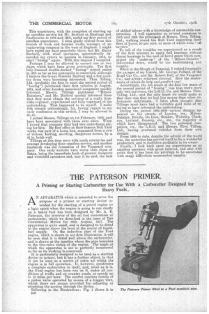
AN APPARATUS which is intended to serve the purpose of a primer or starting device intended for the-starting of a petrol engine on a light spirit when the engine, is going to run chiefly on a, heavy fuel has been designed by Mr. A. D. Paterson, the inventor of the oil fuel -economizer or carburetter, which we described in the issue of TEE COMMERCIAL MOTOR for 30th August, 1917. The apparatus is quite small, and is designed to be fitted to the engine above the level of the source of liquidfuel supply. On the induction .pipe ofthe Ford engine, which is shown in our first illustration, it will be seen that it is fitted well above the carburetter, and is shown at the junction where the pipe branches to the two-valve chests of the engine. The angle at which the apparatus is set is perfectly immaterial so far as its working is concerned. it is particularly designed to be used as a starting device or primer, but it has a further object, in that it can be used as a source of extra air whilst the engine is in full operation. It, however, constitutes a complete carburetter in itself, and, small as it is, the Ford engine has been run on it, under all conditions of traffic and on country roads, at speeds up to 15 miles _per hour. The control consists merely of a piston valve operated by means of a trigger wire, whilst there are means provided for adjusting or steadying the suction through the device.
Referring to the illustrations : Fig. 1 allows it in ii30
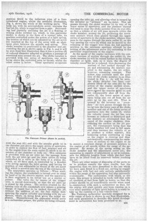
position Attdd to the induction pipe of a fourcyliadered engine, whilst the sectional illustration, lig. 2, shows the whole of the working Parts. The body (a), with its screwed-down cover, contains the, fuel jet (b), which is supplied from a pipe. Surrounding and partially enclosing the jet is a floating or mixing choke member (c), which, in this particular model, is shown in the form of a, venturi tube,. its .position controlled under the action of a light spring, the tension of which can be adjusted by the set screw (c1) inserted at the top of the cover with an abutment plate between the spindle and spring. This choke member (c) positioned in the chamber and surrounding the jet is shown again in Fig. 3, and it will be seen from-this illustration that it has a portion (d) of reduced diameter adapted to produce a passage of restricted area around the jet. The choke member is provided with two series of apertures, one series being above the restricted area or throat, whilst the other series is below. These apertures co-operate with the seat (d1) and with the annular guide (e) in the chamber just above the upper series of apertures, in order to control the flow of fuel mixture and air to the engine from the main outlet 0) which is an extension of -the chamber or body (a). This extension is provided with an air inlet (g), the passage from both the air inlet. (g) and the main outlet (f) being controlled by a valve in the form of a piston (h), which, as we have said, is-controlled by a Bowden wire acting against the inlet. spring, and having its position of rest adjustable by means of the set screw (4), which is screwed into the top of the extension (f). The apparatus operates as follows :—When Starting the engine, the crankshaft is turned over as usual by hand or by the electric starter, and the apparatus is then employed in its initial 'use as a starter or primer. The valve (h), by _means of the trigger wire, is moved downwards, so that the air inlet (g) is closed by the piston. The suction .created by. the turning over of the crankshaft now causes. a priming charge of liquid_ fuel to be sucked through Jhe jet without the addition of air, the fuel charge then entering the engine cylinder and -mixing with the air therein, which, on -being fired,gives the initial explosion. Thenceforward the apparatus would serve as a carburetter proper, the piston (b) being released,
opening the inlet (g), and allowing what is termed by the inventor as " primary" air to enter. This air passes through the choke member (c) by way of its lower series of apertures, and the pressure thereof will tend to raise the choke member from its seat (di), so that a volume of air will pass upwards within the choke in j ember, around the et, producing the necessary mixture which then passes through the uppei series of apertures in the choke member, whence they pass to the engine through the main outlet (f), on the way passing thevalve (10 which can be moved by the releasing of the trigger wire from the full aperture position to the minimum aperture allowed by the setting of.the adjustment screw (hi.) according to the particular requirements of the engine.
As the speed of the engine increases with the constant increase of suction through the outlet (f),, the choke member (c) will be raised further in the mixing chamber or kody, and, as it rises, the degree of velocity round"the jet is reduced, thus decreasing the amount of ,fuel -sucked through the jet and attenuating the mixture sup plied to the engine, the jet orifice, however, remaining constant. This action may continue until the position of the choke member is„as illustrated in Fig. 4. As will be seen, the choke member has been completely lifted off the seat (dl) by the action of the engine suction alone, and the upper series of apertures have pissed the annular guide (e) and are consequently shut off from the outlet (f), the lower series of apertures being also cut off from the air _inlet (g) by the seat (dl). What is termed by the inventor as " secondary " air now passes through the inlet (g) into the lower part of the choke
member and out of the 16wer series of apertures into the outlet (f), whilst the velocity round the jet has now become so reduced or destroyed and the mixture so attenuated that the speed of the engine slackens, thus reducing the suction on the jet proper, the consequence being that the choke member will tend to fall again and thus increase the velocity so as to produce a richer mixture, this balancing action continuing so long as the engine is running and thus automatically compensating for variations of suction to the engine so as to ensure a constant charge of .accurate mixture to the engine at all speeds within the range of the apparatus. By means of the spring acting on the choke member and the adjustment screw (c1), the apparatus is capable of adjustment so ag to -compen sate for different heights from which the.fuel may have to be lifted from its reservoir before reaching the jet. There are other means of disposing of the parts so as to produce exactly the same results, but the apparatus that we have described is the one which
we have seen fitted to a Ford car, serving to supply the engine with fuel not only entirely satisfactorily within the range of the apparatus, but also extremely economically. . The carburetter, with which, in the main, this primer is intended to work, will deal with all qualities of fuel from light to heavy, so that the primer should be of considerable service when used inLeortjunetton with such a carburetter as that, for the engine Will start quickly and keep running on a very small quantity of light spirit before it is ready to take-up the running-on a less 'volatile fuel.
The Paterson carburetter specially designed for a wide range of fuels is shown in our first illustration, and early permission to describe this latest development in carburation has been promised to us.
6