


From Drivers and Mechanics.
Page 26
Page 27
If you've noticed an error in this article please click here to report it so we can fix it.
TEN SHILLINGS WEEKLY is paid for the best communication received, and one penny a line of ten words for anything else published, with an allowance for photographs.
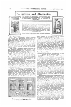
Gudgeon-pin Methods.
[1140] " E.R." (Nottingham) writes :—" Readers will no doubt have experienced, at one time or another, trouble with the setscrews securing the gudgeon pin in position. When these screws come loose they are apt to do damage to the extent of breaking a cylinder or piston. I send you a few ways of securing gudgeon pins which I have come across. The gudgeon pm should in all cases be a light driving fit, and it should have one end .0001 to .0003 larger than the other.
." Fig. 1 shows a very simple method of securing the pin. Here the gudgeon pin must be about a in. shorter than the cylinder bore. This pin should be drilled down each end with a I in. drill to a depth of in. The small part of the brass button shown must be a tight fit in the hole drilled in the gudgeon. "Fig. 2 shows another simple method. A is the piston ; B is the gudgeon pin which should be a good fit. The pin should be fixed tightly in position and a / in. tapping hole about / in. deep drilled in it. The button-headed screw is shown at C.
"Fig. 3 is a good method, and it gives the advantage of an additional piston ring. B is the gudgeon pin, and C is a groove about 3-32nds in. deep. The width of the groove should be slightly larger than the diameter of the gudgeon pin. D. is a concentric ring to fit in groove (0), and it should be fitted as an ordinary piston ring.
"Fig. 4.—Some makers of cylinders simply have the gudgeon pin a driving fit, without any other means of securing it. In such cases the gudgeon pin should be prevented from turning round. B is the gudgeon-pin hole which should be plugged with a piece of mild steel. Dot at C and drill a On. hole about / in. deep. This makes the slot winch runs into the gudgeon-pin hole. Put a / in. silver stee peg in gudgeon pin as shown, so that the gudgeon pin will be prevented from turning round. "Fig. 5 is probably the most efficient form of the setscrew type of fastening Make a pin the same size thread as the original one, but with a longer head. Square a portion of the head as shown and drill a I, in. hole at C. Put the pin in and screw up tight in the usual way. Next make a square hole washer (D) to fit the square head of pin ; then note the section of the washer which touches against the side of the piston. Mark it off and then file the part away, as shown in drawing. When the washer is fitted a stout split pin should be put through the hole C."
Useful Hints and Tips.
The sender of the following conunwnication has been awarded the Ws, prize this week.
[1141] "H.F.B." (Ealing) writes:—"I1 a piece of soft fiat brass or copper be lightly hammered all over on both sides with many light blows, a fairly decent spring will be made. The effect is the same as the hard rolling process, slightly modified. "A useful tip when dealing with a. nut that is rusted in place on the bolt is the following. Heat a piece of steel or iron of about the same diameter as the rusted bolt to a white heat, and apply, while hot, to the end of the bolt. It should be held in contact until it has cooled down a fairish amount, and can then be removed. When the nut and bolt have cooled somewhat, it will be found that the nut can generally be removed without excessive exertion. This is due to the fact that the bolt expands more quickly than the nut owing to the localized heat, and this creates fracture of the rust, making the nut easy to remove.
"Many commercial motorvans and wagons have an unsatisfactory lighting system. This is due to the fact that rubber pipes from the generator to the lamps are the rule. These are not strong enough, and they sag, and are also had conductors for the gas. If the generator be fixed in one position as a general rule, it is not an expensive matter to run brass or copper tubing along where it is needed, to within 2 in. or 3 in. of the lamp. This can be fastened into place by suitable clamps and all connections sweated on. Rubber connections should be made between the ends of the nines and the lamps and generator. "Cases of overheating sometimes occur owing to the fan blades losing their original shape. This occurs in many ways. Sometimes a blade is knocked over when the bonnet is opened for inspection, or stones may hit it, or, when dismantling for examination, the vanes may be slightly put out of shape. The result is that instead of helping to cool the water and engine, the fan is simply a user of power. When this trouble is susnected, a little exneriment should be made by bending the vanes backwards and forwards until a fu'l volume of air is created.
".Many drivers wonder why they cannot make a satisfactory job of grinding in the exhaust, valve. When the job is completed a good seating is made, but within a few hundred miles leakage takes place again. This is often due to the fact that the valve spindle is bent. Before grinding the valve in, it is always a wise plan to run it between lathe centres in order to see whether it is true or not. A few taps with a mallet, will remedy any trouble of this kind."
A Drift for Cotter Slots.
. [1142] "R.T." (Andover) writes :—" It is not unusual to find that when a valve has been turned up and set, it is damaged or entirely spoilt when the cotter slot is being cut. The following description of a simple little method of avoiding this may be of service to some of my fellow-mechanics. A clamp, as shown in the sketch [We have had this re-drawn.—En] gliould be knocked up on the anvil, and it should be tapped to receive a. set screw. A piece of cast steel of the width and thickness of the valve cotter, and about 2i in. long, should next be filed up and gently tapered off. It should then be cut as Shown in the sketch, and carefully hardened and tempered. If this be done with care, such a drift will slot a large number of cotter holes. Great attention must be paid to the drilling of the holes in the valve stem before using the drift. I myself have found that if a hole be drilled and then plugged, and a second hole drilled almost touching the plug, and then the plug knocked out of the stem, a rough slot will be formed, which does not contain much metal for the drift to remove.
'' The valve spindle should be placed in the clamp. and the drift gently screwed down. When it has been pushed right through, a good clean slot will be formed which hardly requires touching with a file."
Repairing the Float.
[1143] " J.D, " (Bristol) writes :—" I am employed as a motorbus driver, and one day last. week I noticed volumes of black smoke coming from the exhaust pipe. I at once thought that this was due to overlubrication, but as it continued I found, after a little investigation, that petrol had got. into the float and the engine was getting too rich a mixture. I examined the float, but could not find any flaw in it. In order to find out where the leakage was, I placed the float chamber on to the exhaust. pipe, which was ver hot, and after a while ran a lighted match round it. and finally discovered a. very minute hole, which was the cause of the trouble. I turned the float upside down on the exhaust pipe, and soon got rid of the petrol owing to the pressure of the heated gas inside. I marked the place with a pencil, and ran a very fine film of soda over it, afterwards polishing off the surplus with a piece of emery cloth. I need hardly say that tinkering with a carburetter float is, at the best of times, a somewhat tricky business, and should a repair resembling the above be attempted, the greatest care must be employed." Synchronizing the L.T. Magneto Ignition, [1144] " B.T." (Andover) writes :—" Users of vehicles fitted with low-tension ignition, while unanimous as to its immunity from electrical breakdowns, sometimes experience inconveniencein obtaining synchronism in four-cylinder engines owing to inequalities in the wcar upon the igniters and the trip gear operating the latter. A simple method of tuning up four-cylinder engines is the following: Obtain an ordinary electric bell and battery, and connect the positive terminal of the battery to one terminal of the bell and the negative terminal of the battery to the cylinder. On turning the crankshaft the bell will commence to ring as soon as the ignition points inside the cylinder uncle/ test make contact. Should, however, no ring occur at the firing point of the cylinder, the adjustment rod should be screwed up until the ringing of the bell makes it clear that the contact is made. When the exact point of ignition is reached, by turning the shaft a -little further the bell will cease to ring. Each cylinder should be timed in turn, and the adjuster rods set until the ignition is broken at the dead centres with the control lever set at the retard position. The timing of the cylinders should be such that a. space of a-bout 4 in. is left between the armature shield and the pole-piece when the piston is at top centre. This is rather important., as these magnetos do not, as is sometimes supposed, generate current. continually, and the maximum current given off must take place simultaneously with the breaking of the ignition.
"There are a considerable number of vehicles still on the road which are fitted with low-tension ignition. To these the above tips will be useful."
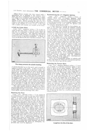
Protecting the Furnace Door.
[1145.1 " E. 8." (Seaham Harbour) writes :—" I send ou a sketch of a fire-hole protector which I have fitted to three of our steam wagons. The cast-iron gland is fitted from the inside of the fire-box, and continues right through the fire hole, being fixed in position by an I in. steel plate, which is fitted to the outside of the casing. This plate has four 4 in. holes drilled in it, and the gland has four 4 in. tapping holes, the whole held in position by 4 in. bolts. A recess is cast on the inside edge of the flange, which clears the rivet heads, thus protecting them from the fire. When this cover is used, many of the every-day fire-box troubles which one meets with on a steam wagon are removed. The gland preserves the fire hole during the whole life of the firebox. The most expensive part of this protector is the making of the pattern, but, when once this is procured, any foundry will cast the necessary plate and gland very quickly. The fitting can-be done by a machine-shop labourer without trouble."