


Reducing Oil Consumption
Page 60
If you've noticed an error in this article please click here to report it so we can fix it.
A Resume of Recently Published Patent Specifications T°prevent excess oil from reaching the combustion chamber is the object of patent No. 398,497, by T. K. Walton and E. G. Kingston, of the Bristol Tramways and Carriage Co., Ltd. Clare Street House, Bristol.
This specification, which is illustrated with 11 different drawings, shows various methods of achieving the desired en.d. The basic principle is in each case the same, viz., the attachment to each side of the big-end bearing of a disc, the diameter of which exceeds that of any other portion of the journal. Oil leaving the bearing will travel outwards along these discs, to be flung off by. centrifugal force. Annular troughs are provided to intercept the stream of oil and return it to the sump.
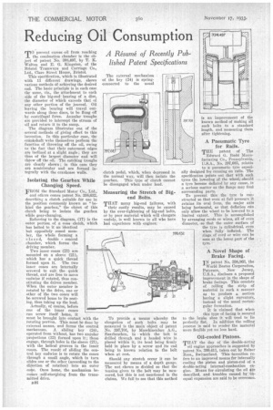
The diagram illustrates one of the several methods of giving effect to this invention. In this particular case, the crankshaft webs themselves perform the function of throwing off the oil, owing to the fact that their outermost edges are inclined at a slight angle; they are thus of the largest diameter and will throw off the oil; The catching troughs are clearly shown; in this case they are semicircular and are formed integrally with the crankcase walls.
Isolating the Gearbox While Changing Speed.
FROM the Standard Motor Co., Ltd.,
and othsrs comes patent No. 398,632, describing a clutch suitable for use in the position commonly known as "behind the gearbox," the object of this clutch being to isolate the gearbox while gear-changing.
Referring to the diagram, (17) is the outer portion of a cone clutch, which has bolted to it an identical
but oppositely coned member, the whole forming a closed, double conical chamber, which forms the driVing member.
Two inner cones (23) are mounted on a sleeve .(21),
which has a quick thread formed upon it. The two inner cones are internally screwed to suit the quick thread, and are free to move endwise if rotated, thus con stituting the driven member.
When the outer member is rotated by the drive, one or other of the two cones will be screwed home to its seating, thus taking up the load. Actually, of course, before one of the inner cones can screw itself home, it must be brought into contact with the rotating portion. This must be done by external means, and forms the control mechanism. A sliding key (24), operated from without, has two angular Projections (32) formed upon it ; these engage, through holes in the sleeve (21), with the helical grooves in the inner. cones. The result of sliding the con trol hey endwise is to rotate the cones through a small angle, which in turn slides one or the other (according to the direction of rotation) into an outer cone. Once home, the mechanism beconies ;self-energizing from the transmitted drive.
1146 clutch pedal, which, when depressed in the normal way, will then isolate the gearbox. This type of clutch cannot be disengaged when under load.
Measuring the Stretch of Bigend Bolts.
THAN many big-end failures, with their costly results, may be caused by the over-tightening of big-end bolts, or by poor material which will elongate iinduly, is well known to all who have had experience with engines.
To provide a means whereby the elongation of such bolts may be measured is the main object of Patent No. 397,701, by Masehinenbau A.G., Saarbrucken, in • which the bolt is drilled through and a headed wire is placed within it, its head being firmly held in place by a screw and its end being in known relation to the bolt when at rest.
Should any stretch occur it can be measured by means of a depth gauge. The nut shown is divided so that the tension given to the bolt may be measured, but this is not mentioned in the claims. We fail to see that this method is an improvement of the
397701 known method of making all such bolts to a standard length, and measuring them after tightening.
A Pneumatic Tyre for Rails.
THE patent of The Edward G. Budd Manufacturing Co., Pennsylvania, U.S.A., No. 397,685, relate's to a pneumatic tyre especially designed for running on rails. The specification points out that with such tyres the lowering of the wheel,. should a tyre become deflated by any cause, is a serious matter as the flange may foul surrounding parts.
To prevent this the tyre is constructed so that even at full pressure it retains its oval form, the major axis being horizontal, so that deflation can only allow the wheel to be lowered to .a limited extent. This is accomplished by arranging cords or wires, all of even diameter,•so that the outer surface of the tyre is cylindrical, even when fully inflated. The rings, of cord or wire can be seen at the lower part of the tyre.
A Novel Shape of Brake Facing.
IN patent No. 398,863, the
World Bestos Corporation, Paterson, New Jersey, U.S.A., discloses a proposed improvement in the shape of brake facings. This consists of rolling the strip of material in such a manner as to produce a section having a slight curvature, instead of the usual rectangular formation.
It is -claimed that when this type of facing is secured to the brake shoe it will tend to' lie perfectly flat. In addition the rolling process is said to render the material more flexible yet no less hard.
Oil-cooled Pistons.
THAT the day of the double-acting,
oil engine approaches is suggested by patent No. 399,411, taken out by Sulzer Bros., Switzerland. This invention refers to an improved means for internally cooling the piston and piston-rod of a donble-acting internal-combustion eti.gine. Means for circulating the oil 46 described, and troubles caused by unequal expansion are said to he overcome.