


IMPROVEMENTS IN VALVES AND THEIR GEAR.
Page 32
If you've noticed an error in this article please click here to report it so we can fix it.
A Résumé of Recently Published Patent Specifications.
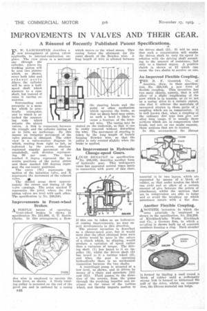
F. W. LANCHESTER describes a new arrangement: of piston valves applicable to internal-combustion engines. The view given is a sectional one through the
cylinder. Above the working piston will be seen two pistons which, as shown, cover both inlet and exhaust ports. Above the cylinder will be seen a halfspeed shaft which answers to a camshaft, but instead of cams it carries eccentrics.
Surrounding each eccentric is a member which is practically triangular, and to which is attached the connecting rods which actuate the piston valves. A link is connected, between the triangle and the cylinder casting so as to form an anchorage. By this means an irregular movement of the valve pistons is obtained. The other view is a valve-motion diagram in which, reading from right to left, as indicated by the arrow, abscissa represent angular movement of the crankshaft, each division representing 60 per cent. The lines marked 0 degree represent the incentre positions of the motor piston and those marked 180 degrees represent the out-centre positions.
The curve (W) represents the motion of the induction valve, and X represents the movement of the exhaust
valve. 4, The shaded areas show approximately the extent and timing of the valve Lpenings. The point marked T represents the point where the two piston valves arc level with each other. The specification is No. 240,540.
Improvements in Front-wheel Brakes.
A SIMPLE means of operating front-wheel brakes is shown in specification No. 241,006, G. T. SmithClarke. In this arrangement a Bow
den wire is employed to operate the brake lever, as shown. A freely rotating pulley is mounted on the end of the pivot pin and is enclosed by a casing which moves as the wheel steers. This casing forms the abutment for the outer sheath of the Bowden wire. A long length of wire is allowed between
the steering heads and the pedal or other mechanism which operates the brake, so that no sharp bend may occur, as such a bend is likely to cause a fracture of the internal wire. The casing may be slotted on the underside, so that it can be easily removed without disturbing the wire. The movement of steering is taken by the long length of loosely hanging Bowden wire, so that the pulley is only rotated slightly when the brake is applied.
An Improvement in Hydraulic Change-speed Gears.
LOUIS RENAULT in specification No. 236,886, describes another form of hydraulic gear. This well-known name has appeared several times lately in connection with gears of this class.
If this can be taken as an indicatio of coming improvements, we may exPeet developments in this direction. The present invention is described as a change-speed gear, but it would seem that the effect obtained from such a device would be more in the aatare of a clutch which, by slipping, would produce a variation of speed rather than a variation of torque. The driving shaft (1) has keyed to it an impeller (4), whilst the driven shaft (2) has keyed to it a turbine wheel (6). and when the gear is operating hydraulically there is no mechanical connection between the two shafts.
A centrifugal pump is situated at a low level, as shown, and is driven by means of a chain and sprockets (10) and (11). Fluid passes, in the direction of the arrows, from the pump through the revolving impeller and impinges on the vanes of the turbine wheel, and thereby imparts motion to the driven shaft (2). It will be seen that such a transmission will enable the driven shaft to vary its speed in relation with the driving shaft according to the amount of resistance, 'but only to a limited degree. A positive clutch is shown at 13 which can cause the two shafts to revolve as one.
An Improved Flexible Coupling.
THE B. F. Goodrich Co., of ; America, show, in their ,specifica ; tion No. 228,100, a new form of dexible coupling. This invention has two main objects, namely, that it will allow of a slight lengthening of the part which is in tension, so as to act as a spring drive to a certain extent, also that it relieves. the materials of unwanted strains in those parts of a coupling which are in compression. It is well known that, when a coupling of the ordinary disc type does give out after long usage, it is usually those sections which are in compression that break, and not, as one might suppose, those sections that are in tension.
In this arrangefnent the fibrous material is in two layers, which are separated by means of a block of rubber, so that under tension the block can yield and so allow of a certain amount of give between the -points of attachment, whilst the sections that are in compression are able to bulge and so avoid • the breaking up which sometimes occurs with a fiat disc.
Another Flexible Coupling.
ANOTHER invention in which the same principle is employed is shown in the specification, No. 224,209, of Kirchbach'sche Werke Xirchbach and Co., a German firm, in which a cezpling is shown built up of separate members forming a ring. Each member is formed by binding a cord round a block of rubber until a sufficiently strong link is formed to withstand the pull of the drive,' whilst, on compression, the fibrous material can bulge.