


AN ALL-METAL FLEXIBLE COUPLING.
Page 62
If you've noticed an error in this article please click here to report it so we can fix it.
A Résumé of Recently Published Patent Specifications.
TTNIVERSAL joints which depend upon the flexibility
of the material of which some part of them is composed have several points which should recommend them to users of commercial motors. In the first place they require no lubrication (and neglect of lubrication iS the bugbear of the manufacturer and designer of eommercial vehicles). Secondly, they are extremely simple and easy to renew at a low cost. They appeal to that class of user who thinks that the only time that any part of his vehicle should receive attention is when it will go no farther. In such a ease as this, a spare flexible part can be carried by the driver, and when the last hour of service has been got out of the old part the new one can be put in place on the road. These are the good points of flexible couplings, but now for their bad points. Materials such as leather, canvas interlaid with rubber, etc., are flexible, but the veryfact of their flexibility is sure to be accompanied by a certain tendency to stretch and as the stretching of such materials is apt to be uneven, there is always the risk of a cardan shaft becoming eccentric, which, in the comparatively heavy shafts necessary for commercial work, means unpleasant vibration.
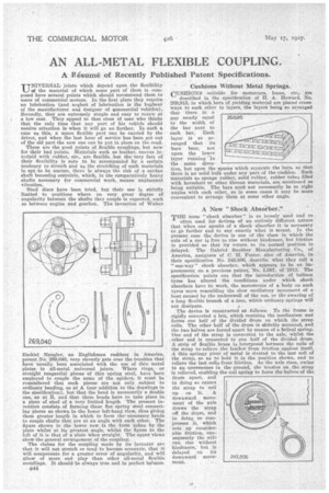
Steel discs have been tried, but their use is strictly limited to positions where no very great degree of angularity between the shafts they couple is expected, such as between engine and gearbox. The invention of Walter Ezekiel Nangler, an Englishman resident in America, patent No 269,040, very cleverly gets over the troubles that have usually been associated with the use of thin metal plates in all-metal universal joints. Where rings, or straight tangential pieces of thin spring steel, have been employed to couple the arms of the spiders, it mnst be remembered that such pieces are not only subject to ordinary bending, as at A (our addition to the drawings in the specification), but that the bend is necessarily a double one, as at B, and that these bends have to take place in a piece of steel of a very limited length. The present invention consists of forming these flat spring steel connecting pieces as shown in the lower left-hand view, thus giving them greater length in which to form the■necessary bends to couple shafts that are at an angle with each other. The figure shown in the lower row is the form taken by the plate whilst at its greatest angle, whilst the figure to the left of it is that of n plate when straight. The upper views show the general arrangement of the coupling. The claims for the coupling made by its inventor are that it will not stretch or tend to become eccentric, that it will compensate for a greater error of angularity, and will allow of more end play than other all-metal flexible couplings. It should be always true and in perfect balance 844
' Cushions Without Metal Springs.
CUSHIONS suitable for motorcars, buses, etc., are
described in the specification of H. A. Howard, No. 268,915, in which bars of yielding material are placed crossways to each other in layers, the layers being so arranged that there is a gap nearly equal to the width of the bar next to each bar. Each layer is so arranged that its bars bear, not upon the lower layer running in the same direction, but upon the spaces which separate the bars, so that there is no solid bulk under any part of the cushion. Such materials as sponge rubber, solid rubber, rubber tubes filled with horsehair or other fibrous materials, are mentioned as being suitable. The bars need not necessarily be at right angles with each other, as in some cases it may be more convenient to arrange them at some other angle. " P 5lIPAR.V0•41:1,07 411RPA111.■ • NIA. • L'4'00 r tiNCJIr 1Z1,411:1511 ; A New "Shock Absorber."
THE term " shock absorber" is so loosely used and so
often used for devices of an entirely different nature that when one speaks of a shock absorber it is necessary to go farther and to say exactly what is meant. In the present case the device is one of the class in which. the axle of a car is free to rise without hindrance, but friction is provided so that its return to its normal position is delayed. The Gabriel Snubber Manufacturing Co., of America, assignees of C.11. Foster, also of America, in their specification No. 245,806, describe what they call a " one-way" shock absorber, which appears to be an improvement on a previous patent, No. 1,587, of 1912. The specification points out that the introduction of balloon tyres has altered the conditions under which shock absorbers have to work, the movements of a body on such tyres more resembling the slow oscillatory movement of a boat caused by the underswell of the sea, or the swaying of a long flexible branch of alrec, which ordinary springs will not dissipate.
The device is constructed as follows. To the frame is rigidly connected a box, which contains the mechanism and forms one half of the divided drum on which the strap coils. The other half of the drum is alidaldy mounted, and the two halves are forced apart by means of a helical spring. One end of the strap is connected to the axle, whilst the other end is connected to one half of the divided drum. A strip of flexible brass is interposed between the coils of the strap to,relieve the leather from friction against itself, A thin springy piece of metal is riveted to the last coil of the strap, so as to hold it in the position shown, and to relieve the last coils from friction. As the axle rises, owing to an unevenness in the-ground, the tension on the strap is relieved, enabling the coil spring to force the halves of the drum apart, and in doing so causes the strap to coil up on it. A downward movement of the axle draws the strap off the drum, and in doing so compresses it, which sets ,up considerable friction, consequently the axle can rise without hindrance,' but is delayed on its downward movement.