


A NEW CARBURETTER.
Page 32
If you've noticed an error in this article please click here to report it so we can fix it.
A Résumé of Recently Published Patents.
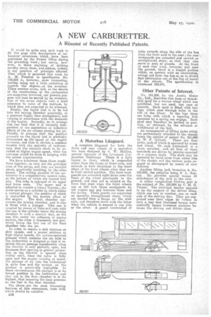
It would be quite easy each week to fill this page with descriptions of carburetter inventions which, have been published by the Patent Office during the preceding week; but rarely, however, is there anything of striking novelty about them, and seldom, indeed, is any question :of principle affected. That which is patented this week by A. M. Prentiss in specification No. 160,925 is, however, most interesting, besides being not a little ambitious as regards the obeectseof the inventor. These number seven, and, as the details of the construction of the ,carburetter are somewhat involved, our present purpose will best be served by an enumeration of the seven objects with a brief reference to some of the methods by which they are expected to be attained.
Firstly, the liquid fuel is to be fed into the mixing chamber positively, at a pressure higher than atmospheric, and varying in accordance with the demands of the engine. Secondly, so to arrange this fuel feed that it is virtually independent of the .aspirations or induction effects of the air column passing the jet. Thirdly, to arrange that the positive pressure on the liquid fuel is gradually diminished as the speed of the engine increases, and thus to obviate a common trouble with the majority of carburetters' that the mixture tends to be enricheded at higher engine speed, when the converse would be more in keeping with the actual requirements.
We have bracketed these three conditions together, as they are the principal ones of the seven, and they are brought about, practically. speaking, by the same means. The mixing chamber of the carburetter is.a comparatively narrow tube, at the bottom of which are located four jets. The tube is enlarged at its upper
and lower ends. The upper end is adapted, to contain a, rotary throttle; the lower serves as a cylinder in which slides a vertical plunger, the position of which is controlled by the suction effect of
the eugine. The float chamber surrounds the mixing chamber, and it also is fitted with a plunger. This one is coupled by means of links and rode with the one in the cylinder below tho mixing chamber in such a manner that, as the one lifts under the influence of engine suction,. the other is depressed, and positively forces the fuel out of the float chamber into the jet.
. In rorder to ensure a rich mixture at slow speeds, and a poorer mixture at high engine speeds, the suction-operated plunger which contains the air inlet to the carburetter is designed so that it restricts the air passage considerably when thfs throttle is only partially open, but increases that opening in greater proportion as the throttle is opened more _widely until, when the valve is full open and the engine sunning at speed, the passage of air into the carburetter is quite free and the suction on the plunger is practically negligible. In these circumstances the plunger is at its lowest position in the carburetter and that one in the float chamber is at its highest, thus imposing the least pressure on the fuel in the float chamber, The above are the most interesting features of this component, tests with which should be valuable.
B36
A Motorbus Lifeguard.
A complete lifeguard for both the front and rear wheels' of a motorbus has been designed by C W. general manager of the Liverpool Corporation Tramwaye. There is a light fender in front, which is suspended either from the frame or front axle, and extends in both directions to the inner edges of the front wheels when they are in their central positioe. The front mudguarda are extended right down over the front of the wheel practically to the ground, and they are so shaped at the front that even when the front wheels are at full lock these niudguards do not expose any gap between them and the fender. These guards are supported on specially strengthened stays, which are carried from a flange on the stub axle, and therefore move with the latter when the vehicle is steered to one side or the other. A guard constructed of
laths extends along the side of the bus from the front axle to the rear ; the rear mudguards are extended and carried an strengthened stays, so that they also serve in part as guards. At the front of each rear wing, however, and near the ground, there is a, hinged portion which, on contact with an obstruction, swings out from the bus so as to divert that obstruction out of the line of travel of the wheels. The specification is numbered 160,871.
Other Patents of Interest,
No. 161,024, by the Austin Motor Co., Ltd.' describes that form of detachable spud for a tractor wheel which was exhibited, but not used, last year at Lincoln. Each spud is -fitted with two lugs, which pass through holes in the rim of the wheel. In the lugs there are holes with which a tapering bolt operated by a spring can engage. Each spud may therefore be latched in position, or released, by the advance or withdrawal of the bolt.
An arrangement of lifting jacks which are permanently attached to the ohassis forms the subject of patent No. 161,000
by W. F. Cottrell. There 4re four jacks, each of which is operated by worm and wheel. On each worinshaft is a chain sprocket, and all four of these sprockets are driven by pin ions mounted on a common shaft. The shaft may be operated by hand lever from either side of the chassis and the various jacks engaged or disengaged by means of claw clutches.
Another lifting jack invention is No. 160,893, the patentee being F. L. Rap. son, He provides special means of attachment of the jack to the axle. A rather complicated friction gear is the subject of No. 160,864 lay C. M. C. Turner. The principal feature appears to be the support of the driven discs, which are two in number, one on each side of the driving disc. They are supported near their edges by rollers in such a way that increased torque automaticaley causes increased pressure between the. driving and driven discs.