


18. — Removing Leyland Timing Wheel.
Page 30
Page 31
If you've noticed an error in this article please click here to report it so we can fix it.
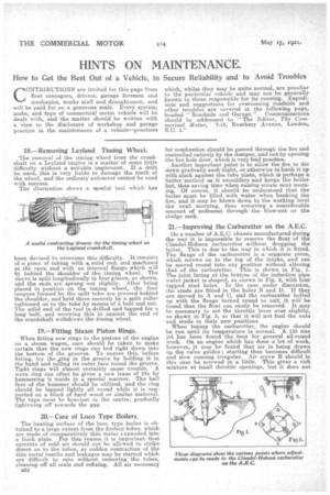
The removal of the timing wheel from the crankshaft on a Leyland engine is a matter of some little difficulty without a suitable implement. If a drift beused, this is very liable to damage the teeth of the wheel, and the ordinary extractor cannot be used with success. The illustration shows a special tool which has been devised to overcome this difficulty. It consists of a piece of tubing with a solid end, and machined at the open end with an internal flange which will fit behind the shoulder of the timing wheel. The sleeve is split longitudinally in four places, as shown, -and the ends are sprung out slightly. After being placed in position on the timing wheel, the four tongues formed by the split tube are pressed behind the shoulder, and held there securely by a. split collar tightened on to the tube by means of a bolt and nut. The solid end of the tool is drilled and tapped for a long bolt, and screwing this in against the end of the crankshaft withdraws the timing wheel.
19.—Fitting Steam Piston Rings.
When fitting new rings to the pistons of the engine on a steam wagon, care should be taken. to make certain that the new rings can bed right down into the bottom of the. grooves. To ensure this, before fitting, try the „ring in the groove by holding it in the hand and rolling its outer face round the groove. Tight rings will almost certainly cause trouble. A worn ring can often be given a new lease of life by hammering it inside in a special manner. The ball face of the hammer should be utilized, and the ring should be tapped lightly all round while it is supported on a block of hard wood or similar material. The taps must be heaviest in the centre, gradually lightening off towards the gap.
20.—Care of Loco Type Boilers.
The heatingsurface of the loco. type boiler is obtained to a large extent from the firebox tubes, which are made of comparatively thin metal expanded into a thick plate. For this reason it is important that currents of cold air should not be allowed to strike direct on to the tubes, as sudden contraction of the thin metal results and leakages may be started which are difficult to cure without removing the tubes, cleaning off all scale and refixing. All air necessary B34 for combustion should be passed through the fire and controlled entirely by the damper, and not by opening the fire hole door, which is very bad practice. Another important point is to allow the fire to die down gradually each night, or otherwise to bank it up with slack against the tube plate, which is perhaps a, better method as it smoulders and keeps the boiler h,ot, thus saving time when raising steam next morning. Of course, it should be understood that the boiler must be filled with water when banking the fire, and it may be blown down to the working level the net morning, thus removing a considerable amount of sediment through the blow-out or the sludge cock.
21.—Improving the Carburetter on the A.E.C.
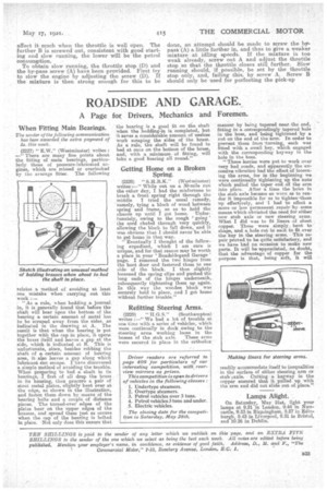
On a number of A.E.C. chassis manufactured during the war it is impossible to remove the float of the Claudel-Hobson carburetter without dropping the latter. This is due to the way in which it is fitted. The flange of the carburetter is a separate piece, which screws on to the top of the intake, and can be moved round into any position without altering that of the carburetter. This is shown in Fig. 1. The joint facing at the bottom of the induction pipe water jacket is shaped, as shown in Fig. 2, with four tapped stud holes. In the case under discussion, the studs are fitted in the holes B and D. If they are moved to A and C, and the carburettor bolted up with the flange turned round to suit, it will be found that the float can easily be removed. It may be necessary to set the throttle lever over slightly, as shown in Fig. 3, so that it will not foul the nuts and studs in their new positions. When tuning the carburetter, the engine should be run until its temperature is normal. A 125 size jet has been found the best for general all-round work. On an engine which has done a lot of work, however, it may be found that air is being drawn up the valve guides; starting then becomes difficult and slow running irregular. Air screw B should in this case be, screwed in a little. This gives a rich mixture at small throttle openings, but it does not affect it much when the throttle is well open. The further B is screwed out, consistent with good starting and slow running, the lower will be the petrol consumption.
To obtain slow running, the throttle stop (D) and the by-pass screw (A) have been provided. First try to slow the engine by adjusting the screw (D). If the mixture is then strong enough for this to be
done, an attempt should be made to screw the bypass (A) a little further in, and thus to give a weaker mixture at idling speeds. If the mixture is too weak already, screw out A and adjust the throttle stop so that the throttle closes still further. Slow running should, if possible, be set by the throttle stop only, and, failing this, by screw A. Screw B should only be used for perfecting the pick-up