 1
1 2
2 3
3 4
4 5
5 6
6 7
7 8
8 9
9 10
10 11
11 12
12 13
13 14
14 15
15 16
16 17
17 18
18 19
19 20
20 21
21 22
22 23
23 24
24 25
25 26
26 27
27 28
28 29
29 30
30 31
31 32
32 33
33 34
34 35
35 36
36 37
37 38
38 39
39 40
40 41
41 42
42 43
43 44
44 45
45 46
46 47
47 48
48 49
49 50
50 51
51 52
52 53
53 54
54 55
55 56
56 57
57 58
58 59
59 60
60 61
61 62
62 63
63 64
64 65
65 66
66 67
67 68
68 69
69 70
70 71
71 72
72 73
73 74
74 75
75 76
76 77
77 78
78 79
79 80
80 81
81 82
82 83
83 84
84 85
85 86
86 87
87 88
88 89
89 90
90 91
91 92
92 93
93 94
94 95
95 96
96 97
97 98
98 99
99 100
100 101
101 102
102 103
103 104
104 105
105 106
106 107
107 108
108 109
109 110
110 111
111 112
112 113
113 114
114 115
115 116
116 117
117 118
118 119
119 120
120 121
121 122
122 123
123 124
124 125
125 126
126 127
127 128
128 129
129 130
130 131
131 132
132 133
133 134
134 135
135 136
136 137
137 138
138 139
139 140
140 141
141 142
142 143
143 144
144 145
145 146
146 147
147 148
148 149
149 150
150 151
151 152
152 153
153 154
154 155
155 156
156 157
157 158
158 159
159 160
160 161
161 162
162 163
163 164
164 165
165 166
166 167
167 168
168 169
169 170
170 171
171 172
172 173
173 174
174 175
175 176
176 177
177 178
178 179
179 180
180 181
181 182
182 183
183 184
184 185
185 186
186 187
187 188
188 189
189 190
190 191
191 192
192 193
193 194
194 195
195 196
196 197
197 198
198 199
199 200
200 DO YOU KNOW YOUR AIR BRAKES?
Page 99
Page 100
Page 101
Page 102
Page 107
If you've noticed an error in this article please click here to report it so we can fix it.
BY HANDYMAN
WHETHER we like it or not, brakes and their efficiency will occupy a good deal of our time and thoughts in the months ahead, and a look at the proposed foot and handbrake retardation ratings makes it quite clear that stopping efficiency will need to be kept up to scratch, since it is evident that we will be permitted to carry only the weights that we can stop. I feel I may be able to help in this search for top performance by highlighting braking system features that can effect efficiency. For this purpose, I have selected items of importance from the recent series, Know Your Air Brakes.
Probably your introduction to air brakes will be when shoes need adjustment. The brake slack adjuster is obviously a brake arm on the operating camshaft. But less obvious is the fact that it has its own built-in adjuster.
The boss of the arm contains a worm wheel which is splined directly on to the camshaft. The wheel is operated by a wormshaft turning in the body of the adjuster and the hexagon head of the wormshaft is turned to make adjustment.
This hexagon is locked by a spring-loaded sleeve partly covering it and the sleeve must be depressed by the spanner or socket before adjustment can be made. As the spanner is removed the sleeve will return to its locked position.
These adjusters are at the mercy of the weather and should be periodically serviced. As indicated by Westinghouse, they will operate 10,000 miles between services, although in wintry conditions it is of value to service them at monthly intervals, otherwise the sleeve may lock up and make adjustment impossible.
On the American Berg adjuster, almost identical to the British makes, the adjuster hexagon is locked by a flat spring strip encircling the hexagon. This pattern is unaffected by weather "or road conditions, it will not jam or seize and any collected debris can be brushed clear.
All three popular makes—Westinghouse, Clayton and Berg— are fitted with a grease nipple or provision for one, and all can be stripped for overhaul on the removal of the rivets through the boss.
On stripping, inspect carefully for cracks or distortion, worn teeth and so on, and on assembly, grease with a recommended lubricant, ensuring that all parts move freely. If the adjuster has been removed from the camshaft, make sure that when refitted the angle formed by the brake operating rod and the adjuster is not less than 90 deg.
To move on to the driver's point of view he has a lot of brake power, more than he wants sometimes, therefore to him the most important part of the system is the operating valve.
This is designed to deal with the full pressure range and give graduated control. It must also respond exactly to the driver's requirements and enable him to sense or feel by pedal load the exact amount of brake power he is putting on. The valve must hold any pressure called for, and increase or decrease braking power in sympathy with pedal movement.
Therefore, two things apply: pedal movement and pedal load working in harmony to provide the exact response called for in brake power.
The footbrake valve can be a single or double unit, the double valve being used with the latest dual safety system. Each valve is an exact copy of the other and both are operated from a balance beam so that each pedal movement produces an exact synchronized response from both.
On the dual safety system, each valve is coupled to a separate, self-contained system, and the failure of one system does not affect the other.
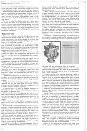
The outline of a standard, foot-operated brake valve can be described as follows: A cylindrical casting which if mounted upright would have the linkage to treadle or pedal at the top, air input port at bottom centre, delivery ports on each side at the bottom, with the exhaust port and its gauze filter midway along the casting.
Starting at the pedal end, there is a plunger acting on a heavy coil spring. This is the graduation spring and pressure on the pedal will compress the spring against a piston. An extension at the base of the piston forms an exhaust valve, which has its seating on a bobbin or spool-like assembly that forms the exhaust valve at the top and the inlet valve at the base.
Both the bobbin valve and the piston are biased by light springs to the upper position, thus the exhaust valve will be open with the piston in the upper "off" position, and air will exhaust up the hollow piston and out through the exhaust port.
Pressure on the pedal will load the graduating spring, which in turn will move the piston. The first downward movement of the piston brings it in contact with the bobbin valve and the exhaust is then closed. Further pedal movement carries the bobbin down against its own spring, opening the centre inlet port to the delivery ports until at maximum pedal pressure the inlet valve is fully open.
Balance
Now we come to the all-important feature of balance. The same pressure that is in evidence at the delivery ports is also acting on the underside of the piston via a drilled passage in a delivery port. The result of this is that the air pressure under the piston reduces the force of the graduating spring by an equal amount.
This causes the piston to rise, followed by the bobbin valve, and because of pedal load the exhaust valve remains closed. By this time, the rising bobbin valve has closed the inlet port and if pedal pressure is held unchanged and steady, a "holding" condition is reached.
In this condition the slightest pedal movement will disturb the balance, so if more brake is needed, pedal pressure will add load to the graduating spring, and in turn the piston will open the inlet valve farther. But if the pedal load is eased fi om the hold position, the piston will leave the bobbin behind in the inlet closed position, and instead the exhaust will open to correspond with spring unload.
This is the modern approach to graduated control of the footbrake, whatever the make of valve. Little is required in the way of maintenance other than lightly oiling the plunger under the rubber boot. If the valve must be stripped, a correct rubber lubricant should be applied to "0" rings and seals.
For testing, there is still no better method than the age-old one of introducing soapy water. If the leak past the exhaust port does not exceed 10 bubbles a minute, the valve is in working order.
Where a drop in efficiency can be expected after a period in service is at the compressor, whether singleor twin-cylinder, and since the designs are very similar we will take the heavier-duty, twin-cylinder water-cooled Westinghouse TU-FLO 500. This is capable of really high speeds, up to 3,000 r.p.m. in fact, with a swept volume of 28 Cu. ft. /min. This represents quite a load, and at a working pressure of 100 lb., 5 h.p. is accounted for.
Lubrication is similar to the Clayton pumps, with only the big ends pressure-fed. On this pump however, it is necessary that the cylinder bores as well as the cylinder heads are water-cooled, therefore the water jacket is very similar to that of the c.i. engine.
Pressure control is arranged through unloader mechanism in the pump. Operating against the inlet valve, a governor valve mounted on the pump, and in circuit with the air reservoir, actuates the unloading Fistons mounted below the inlet valves. These pistons lift and reseat the inlet valves, as the reservoir pressure rises and falls, thus the system is safeguarded and the pump can freewheel when the governed pressure is reached.
An important feature of this pump, particularly in respect of its high capacity, is in connection with the air input side. The air supply can be drawn either from the main engine air cleaner, an antifreeze unit, or the standard Westinghouse strainer, mounted directly on the pump. This strainer protects the pump, ensures long life to valves throughout the system and considerably reduces input noise.
The strainer is packed with curled hair, and at every vehicle service the strainer should be stripped and all parts washed clean, including the curled hair, which should be soaked in engine oil, squeezed dry and repacked. Where the pump has its own lubrication system, this should have the same oil change attention as the main engine.
Unloader valves
Apart from the built-in type of unloader mechanism, separate unloader valve assemblies will be found on certain vehicles, usually chassisor tank-mounted, the main difference being that these valves unload to atmosphere. This type of unloader valve body is a single casting, the governor valve and its adjuster screw forming a threaded assembly in the top of the casting.
The screwed adaptor and the inlet port from the compressor comes in midway at the side, with the delivery port opposite. The exhaust valve assembly and the vent to atmosphere are at the base of the casting.
Air arriving at the inlet port from the compressor passes through the filter just inside the screwed adaptor, and travels across the body to the non-return valve positioned in the delivery port adaptor. Pressure on this valve overcomes the valve spring, the air then passing straight out of the delivery port to the reservoir.
Above this non-return valve is mounted the governor ball valve, which has a top and bottom seating and a small vent to atmosphere at the side. Therefore the chamber of the governor valve is at atmospheric pressure the whole time the ball valve is held on the bottom seating by its compression spring above.
A small drilled passage from the head of the centrally positioned unloader valve communicates with the governor valve chamber. Therefore the head of the unloader valve chamber is also at atmospheric pressure with the ball on the bottom seating.
In the operating sequence, the governor valve is held on the lower valve seat by its own spring, which means that air pressure from the reservoir is already behind the non-return and has access to the underside of the ball valve through a small drilled passage connecting the delivery port to the governor ball valve chamber.
As the compressor charges the reservoir and maximum working pressure is reached, the ball valve spring is overcome, the ball is lifted from the lower seat to the upper one, and the vent to atmosphere is closed. Full pressure is then admitted to the governor valve chamber and also to the head of the unloader valve via the small drilling.
This pressure at the head of the unloader valve is acting against the exhaust valve spring in the base of the valve, and as the air .pressure overcomes the spring pressure the unloader valve moves down. The exhaust valve, which is actually the other end of the unloader valve spool, moves from its seat and the excess air passes through to atmosphere via a check valve designed to keep dirt from entering the exhaust valve.
The governor valve
The governor valve stays open, with the ball on the upper seat, until the reservoir pressure drops to 90 p.s.i. Then, as the governor spring regains control, the ball moves again to the lower seat, closing off the air pressure and again opening the vent to atmosphere via the open, upper valve seat.
At the same time, the air pressure on the head of the unloader valve is exhausted to atmosphere, that valve regains its upper position from the lift of the exhaust valve spring, and the exhaust valve is closed, the air from the compressor once again moving through the non-return valve to the reservoir.
Relay and relay emergency valves seem to receive considerable criticism, and need a little understanding. Both have the same features on the relay side, so we will examine the relay emergency valve.
Here we have a valve body and cover, and, starting from the base of the valve, there is a cap nut, coil spring and the pressureregulating valve. Retained by the cover is the emergency diaphragm, which is spring-loaded, then the lower emergency valve and valve stem to the upper emergency valve, again very similar in layout to the relay valve.
The spring-loaded regulating valve is set to operate at around 70 p.s.i. and in the body of the valve there is a non-return valve retained by a cap nut. An important feature in the emergency line inlet port is a metal filter intended to stop the entry of dirt or abrasive material.
Compressed air passes along the emergency line into the relay emergency-valve via the filter, lifting the non-return valve, then over the top of the emergency diaphragm and on to charge the trailer reservoir.
During this time air has been passing below the emergency diaphragm and into the space above the pressure regulating diaphragm, and air will continue to flow until a pressure of 70 p.s.i. is reached above the regulating diaphragm.
At this point, with 70 lb. above the regulating diaphragm, the regulating valve spring is overcome, the diaphragm moving down and opening the regulating valve.
Air will then flow past both regulating valve and non-return valve and will charge and balance the trailer reservoir to the tractive unit reservoir pressure. As long as the pressure is above 70 lb. the regulating valve will stay open and air is free to flow and retain balance.
Either normal uncoupling or failure of any part of the emergency line will bring the emergency valve into operation as follows:—
As the brake line is broken, compressed air below the emergency diaphragm will escape via the break in the line, and as the pressure drops the non-return valve and the pressure regulating valve will close and hold the air in the trailer reservoir. The pressure then depresses the emergency diaphragm, closing the upper emergency valve and opening the lower valve to the brake cylinders.
With the passage now blocked at the supply valve and the upper emergency valve, the full trailer reservoir pressure can now pass through the valve and apply full brakes. The brakes will stay on until all pressure is released by "blowing" the trailer reservoir or recoupling the emergency line.
Recoupling has the effect of placing pressure again under the emergency diaphragm, lifting the emergency valve and permitting the air trapped in the brake cylinders to flow to atmosphere via the exhaust side of the valve, and at the same time charging and balancing the system.
A driver picking up a strange trailer can carry out a simple test to ensure that all is in order. He should couple up, run the engine and fully charge the system, close the cut-out valve in the emergency line and then disconnect. This should bring the trailer brakes on instantly. Then he should check for any sound of leakage at the emergency valve exhaust, and on recoupling and opening the cutout valve the trailer brakes should release at once.
Check valves play a most important part in the modern' air brake system, and we should have a look at the double-check valve found on the latest plated units.
Where it is necessary to control braking by separate valves— foot pedal or hand lever—there has to be a means of isolating one operating line from the other. This is achieved very simply by the double-check valve, a three-piece body with bracket for chassis mounting.
The valve has a straight-through passage in the form of a bush, with a bobbin or shuttle acting as the free valve, the end caps of the valve body each retaining a seal. The free bobbin can register on one or the other and seal off either end of the valve body.
There is a centrally arranged port to deliver air from either control to the wheel chambers. Each end of the valve accepts a line direct from a control valve, and the action of the double-check valve is simple and reliable.
On one or the other of the operating valves being opened, air will flow into the double-check valve and push the free bobbin to the other end of the valve body, sealing off that end of the valve.
The length of the bobbin is such that it is clear of the outlet port when at either end and therefore the air that has driven the bobbin to the opposite end of the valve will hold the bobbin on its seat and at the same time feed the brake chambers. If the first operating valve is closed and the second opened, the bobbin will change ends and air will flow again to the wheel chambers.
In the event of both operating valves being opened at the same time, the higher pressure will move the bobbin and only one control will apply.
This valve should always be mounted in the horizontal position, and should have an occasional nip-up to ensure there are no leaks at the seals. To test the valve for leakage in the lines it is necessary to apply soap suds to the exhaust ports of the control valves. Then, if on operating a valve, the leakage exceeds one bubble a second, the seals in the double-check valve should be renewed.
If the double-check valve is unable to seal a line fully—for instance, when the foot-control valve is opened—the leakage will show at the exhaust port of the hand-control valve and vice versa.
Similarly, to test the action of the valve, apply the foot control and note that all brakes are operating fully. As the footbrake is released, so should all brakes release smartly. On application of the hand-control valve, the trailer brakes should operate fully and again release cleanly. This indicates that the double-check valve is in good order.
This last test does apply to pre-plated units. On plated equipment, which I will cover later, the hand control operates the separate safety system, and is now arranged to operate the tractive unit driving axle brakes as well as the trailer brakes.
Another air unit playing an ever-increasing part today is the pressure regulator, as with more and more use being made of air quite apart from braking, certain safeguards must be introduced into the system to ensure that the use of auxiliary equipment does not deplete the supply to the brakes, or cause build-up to be too slow to meet braking demands.
One exam* is air-assisted steering. Although the Westinghouse pressure steering does not waste air to atmosphere, there is a minimum air requirement, and if other auxiliary items are in use as the engine is started, there can be some delay in obtaining a safe braking pressure throughout the vehicle.
This feature is taken care of by the pressure regulator which, if arranged in the line before the auxiliary reservoir, will ensure that the main system is fully charged and remains so, the regulator not permitting the auxiliary system to drop the pressure in the main system below 60 p.s.i.
This pressure-regulating valve is quite simple and not unlike the governor described earlier. Its base forms a chamber for an horizontal inlet port and a vertical outlet port and valve seat, the base also being arranged as a bracket for chassis mounting.
The domed cover has four-stud-fixing to the base; the cover carries the adjusting screw in the top with the coil spring and seating. Between the two sections and secured by the four bolts is the diaphragm. Secured through the diaphragm is a single valve that opens and closes the outlet port.
Air pressure arriving at the inlet port will meet a resistance below the diaphragm that requires 60 p.s.i. to move. As this pressure increases the diaphragm moves upwards against the spring pressure, in turn lifting the valve from its seating in the lower chamber.
Adjustment is made by slackening off the lock nut and turning the hexagonal-headed screw. Clockwise will increase the pressure and vice versa. Testing is also easy, as any leakage past the diaphragm will show at the small vent hole in the dome cover. This vent hole is situated just above the level of the bolt heads.
Any alteration to the spring setting should be made with the aid of a pressure gauge inserted in the line, by observing the pressure needed to open the valve. The diaphragm will normally serve up to 12 months (or about 50,000 miles) with safety, but should be replaced at that time regardless.
Where a tractive unit is equipped with hydraulic brakes unboosted by air, yet air is required for the trailer, it is not just a matter of fitting a compressor, reservoir and hand control for the trailer brakes. The law requires foot control—over all wheel brakes.
Avoid time lag
Also, time lag at the trailer must be avoided. This is achieved by the fluid-operated air-pressure valve, this serving a second duty in providing a separate hand control to the trailer brakes.
The Clayton Dewandre APV74 reaction valve is in four main parts, the plunger body, the manually operated lever, the reaction diaphragm assembly and the valve housing.
The hydraulic reaction piston is contained within the piston body, being retained by the normal stop washer and circlip. In contact with this piston is the valve plunger, which is actuated by the cable-operated hand lever, dual rubber seals being fitted to both piston and plunger.
The hydraulic port in the base of the unit communicates with the space or chamber between hydraulic piston and plunger, a bleed screw being positioned nearby. A breather tube, also on top of the body, takes care of exhausted air.
The diaphragm is held between the faces of the hydraulic and air sections, and includes an adaptor-and-rod assembly secured at the diaphragm centre by nut and washer and held up to the hydraulic piston by a coil spring.
The valve housing contains the air inlet and exhaust valves (these valves being joined by a flexible shaft), also the valve return spring and the diaphragm spring.
The compressed-air inlet valve gives a two-stage effect, the small first stage valve permitting a light or low hydraulic pressure to operate the reaction valve, while the larger valve, which provides a seating for the small valve, opens for ir aximum braking effort or emergency application when a full air supply is called for at the trailer.
As the tractive unit brakes are applied, fluid from the main hydraulic line builds up behind the hydraulic piston, this piston moving the diaphragm assembly toward the valves. At the same time the atmospheric port in the diaphragm assembly moves into contact with the atmospheric valve and isolates the trailer air line from atmosphere.
As the hydraulic load increases, the air load on the first stage inlet valve is overcome, the valve moves from its seat and compressed air enters the line to the trailer brake chambers. As air is delivered to the trailer brakes, equal pressure is building up in the diaphragm chamber. This force, directed against the valve piston, brings about the reaction effect, which is to move the diaphragm and reaction piston, allowing the inlet valve to close and bringing about the "hold" position.
Thus, on reaching the degree of stopping power required and with pedal steady, pressure to the trailer brakes remains constant and both inlet and exhaust valves are now closed. If more braking effort is called for, further movement of the pedal will increase fluid pressure on the reaction piston and again the balance is upset, the inlet valve being opened and further air pressure delivered until the inlet valve is fully open.
The cable-operated hand control is sensitive to load in the valve as the reaction force is against the pull of the cable, therefore the driver can feel the degree of brake application.
To test, apply the normal soap and water method to the air side, and after assembly bleed the hydraulic section.
Multi-diaphragm chambers
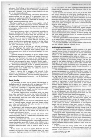
An important change found with plated equipment is the brake chamber, and the Clayton Dewandre dual safety system includes a triple-diaphragm wheel brake chamber. This has the same design features as the single-diaphragm type, but embodies three diaphragms, two operating and one acting as isolator.
From the pressure or sealed end of the air chamber, the first diaphragm is operated by the auxiliary control. The next diaphragm is the isolator, designed to safeguard either operating diaphragm in the event of failure of the other. Between the centre diaphragm and the non-pressure end of the chamber is the service or footbrake diaphragm, coupled through the pushrod to the brake camshaft lever.
A very necessary feature of the triple-diaphragm layout is noted between the diaphragms: two moulded rubber blocks integral with the centre and rearmost diaphragm. These blocks are designed to push the piston rod forward when the auxiliary system is operated; they also speed up brake action and conserve the air supply.
Flexible air lines feed the two separate diaphragms, one fitted in the pressure end for the auxiliary, and one in the body of the chamber for the forward or service line. Special care should be taken when refitting these air-line connections, as the adaptor threaded into the chamber body is tapered, and it is known that excessive tightening can overstrain and split the chamber, which then virtually becomes scrap.
A further point to remember is to avoid brake shoes going too far out of adjustment, and this applies particularly to triplechamber diaphragms where excessive piston rod travel can considerably shorten the life of the block-type diaphragm.
Since the air storage tank appears to need little in the way of attention, it is taken for granted and often suffers neglect. The reservoir has a primary function—to store air in quantity and at a pressure for many uses. Its secondary function, which may not be so well known, is to provide a place where hot air from the compressor can cool and allow oil and water vapours to condense.
Water found in air reservoirs is often considered to be due solely to weather conditions. Compression and later cooling of the air produces the water, although humidity can influence the situation. The oil content is of course from excessive compressor lubrication.
Draining the water should be made a daily duty. Since many reservoir drain taps are of the tapered cone type, and do not take kindly to being submerged too long in water, the rate of failure of the pendant-type lever is high, and for this reason, daily draining iE neglected, no one having a spannei or the time to unscrew the complete tap. It is therefore necessary to include reservoir drair taps on the vehicle inspection sheet, and keep a supply in the store in readiness.
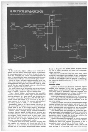
In the basic three-line braking system found on the plate( tractive unit, air flowing from the compressor passes through the unloader valve to the reservoir, being prevented from leaking bad to the compressor by the non-return valve in the outlet from the unloader valve.
From the reservoir, air has free passage to both the treadle valve and the governor valve, as with the system fully charged full pressure is always at these points. As the treadle is operated. pressure flows through the treadle valve via the pipe lines to the wheel chambers front and rear at equal pressure.
In the line to the tractive unit rear brakes, a T-piece is fitted which conveys air to the relay valve at the pressure determined by the treadle position, the air then passing through the open supply valve in the base of the relay valve.
This is brought about by the reservoir pressure having already opened the governor valve, in turn moving the diaphragm in the relay valve and allowing the foot-treadle pressure to pass through a double-check valve to the trailer stand pipe connection. From this point the air passes to the relay valve on the semi-trailer to operate the trailer brakes.
Although 70 p.s.i. is required to open the governor valve, a lower pressure will operate the diaphragm in the relay valve and open the supply valve. Thus when the reservoir is charged, the supply valve will remain open until the auxiliary reservoir is nearly empty.
Since the governor valve closes below 70 p.s.i. two things apply: a safe supply is always available in the auxiliary system in the event of failure in the service line; and should the trailer break away and drop the pressure to zero in the auxiliary section beyond the governor, the diaphragm will close the supply valve, sealing the service line from the break in the standpipe line.
Thus the tractive unit can be brought to a standstill by the residual pressure of 70 p.s.i. in the main reservoir, although at a slightly lower level of efficiency.
This then is the basic footbrake system on the modern tractive unit. We should now examine the auxiliary side to the three line braking system.
As the main air reservoir reaches a pressure of 70 p.s.i., the governor valve is opened and air can flow along both the emergency line and the line to the auxiliary reservoir. If both systems are at a pressure of 95 p.s.i., operating the service line through the foot treadle will draw air from both reservoirs, but if the main reservoir is at only 60 p.s.i., the same brake application will only draw air from the main reservoir.
The same condition applies if the auxiliary hand control is used, as the higher-pressure air would be obtained from both reservoirs, and at the lower pressure from the auxiliary reservoir only.
The foot treadle operates on all road wheels, with the hand control applying pressure to the tractive unit rear and trailer wheels only.
Hand control valve
This auxiliary system is operated by the hand control on the right of the steering column, and air from the auxiliary reservoir flows direct to the hand control and then to the rear wheels of the tractive unit. In that line there is a T-piece, which takes air from the tractive unit wheel line to the stand pipe and palm coupling on the tractor, from where a loop line passes the air to a double-check valve.
As pressure moves the ball across the non-return valve, the line to the relay valve is closed and air flows via the service line to the trailer. With the inclusion of the loop line to the double-check valve the auxiliary system becomes a trailer brake control, as with the . two-line trailer, although with this system there is no separate control of trailer brakes only, the hand control applying equal pressure to the tractive unit driving wheels also.
This is a simple system, and although subjected to some misgivings on its arrival, it is now accepted as a valuable contribution to improved heavy vehicle braking and road safety.
On the arrival of the first three-line systems, a rather odd situation was noted on certain vehicles. This was the fitting of two hand controls on the steering column, and for a while it appeared that this dual method of control would stay; But it was short-lived and the control lever on the near side of the steering column was soon discontinued, as the effect of three-axle braking via the offside hand control soon proved its worth under bad weather conditions.
However, for those who have this dual system. a word on the relay valve used. In the ordinary Way the relay valve is there to give balanced brake power between tractive unit and trailer, but it is adapted on the three-line system to serve as a trailer protection valve, the diaphragm being constantly under pressure to keep the supply valve open.
We should now turn our attention to some of the main stoppages and failures that can occur during a lengthy period in service.
A fairly common bad weather fault is slow pressure build-up: a quick inspection of the unloader valve exhaust would confirm two things—an air leak indicating trouble at the relay piston or ball valve, or excessive oil loss indicating a compressor worn enough at rings or bore to pass oil rather than compressed air.
If all is correct at this point, open the input to the compressor straight to atmosphere without filters, and then check pressure build-up and pumping time, as very often the input filter can be the cause of slow build-up.
With these points cleared and no fault found, it is fairly obvious that a leak exists between compressor, reservoir or brake valve. So clear the obvious points of leakage, first drain cock, pipe joints, hose or warning device. With the engine running it is hard to detect an air leak by sound, yet on stopping the engine no sound may be heard if the fault is between relay valve and pump, and the surest test can still be soapy water applied with a plastic spray bottle.
The compressor-mounted safety valve has fooled most of us at one time cr another by its occasional habit of leaking when the engine is running and causing vibration, so give it a squirt also.
Loss of pressure when stationary is very often traced to the non-return valve section of the unloader, but can be a fault in a brake valve or a loose or cracked joint.
Apart from trouble in the hub section—linings, drums or adjustment—which would show up when either system was operated, and eliminating the possibility of air loss at brake pipes or chambers, two other points mainly contribute to slow brake application: low line pressure which will mean that the brake valve unit requires adjustment, or, quite a common feature, brake pipes that are partially closed and reduced in i.d. by grease and dirt. Here it is often necessary to remove and clean them thoroughly, and with steel pipes, warming them is often the best way to loosen the glue-like coating.
Slow release: With the drum mechanism in order, this fault usually lies in blocked or restricted inlet or exhaust valves, particularly the disc type seating badly.
Binding brakes: If the shoe and expander mechanism is in order, this fault is usually due to a defective brake valve, and air loss will be audible on removing pipes to brake chambers. In the case of sudden and severe retardation on a brake valve being opened slightly, this valve is seriously out of adjustment and should have early attention.
Now here are some tips before and during repair:— • Remember, brake adjustment should only be made at the shoe adjuster. Do not alter the length of piston rods between brake chamber and camshaft, nor take up slack in the handbrake linkage.
• Testing on the bench: Wherever possible, control valves should be tested and adjusted on the bench, but it is important that the air supply used is filtered and dry.
• Cleaning: All metal parts stripped out for overhaul should be washed in a suitable solvent and then blown dry with compressed air, not wiped with dusters or loose woven material.
• Dirt is dangerous: When stripping out air equipment on the vehicle where there is a chance of disturbing caked mud and grit, it is wise to tape up all open pipe ends or valve ports until the actual moment of recoupling.
• Remember before starting a repair that certain air-braked vehicles and most heavy trailers can be standing with the brakes held on by the reservoir pressure and it is most unwise to open any air line before first setting the hand parking brake, or blocking the wheels. Vehicles have moved off when the footbrake line has been opened, causing injury or damage.
• A heavy compressor develops quite a punch when under full load and can work loose. Check and tighten mounting bolts at vehicle service periods.
Let me stress that brakes and brake testing will call for some serious thought in the very near future, and there will be no room for guesswork. At this time it would appear that the answer lies in the roller brake tester.