


A Double-acting Two-stroke
Page 42
If you've noticed an error in this article please click here to report it so we can fix it.
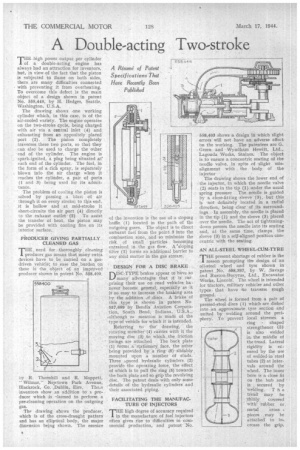
Thigh power output per cylinder of a double-acting. engine has always had an attraction for inventors, but, in view of the fact that the piston is subjected to flame on both sides, there are many difficulties conne.cted with preventing it from overheating. To overcome this defect is the main object of a design shown in patent No. 558,448, by H. Hedges, Seattle, Washington, U.S.A.
The drawing shows one working cylinder which, in this case, is of the air-cooled variety. The engine operates on the two-stroke cycle, being charged with air via a central inlet (4) and exhausting from an oppositely placed port (2). The piston completely traverses these two ports, so that they can also be used to charge the other end of the cylinder. The engine is spark-ignited, a plug being situated at each end of the cylinder. The fuel, in the form of a rich spray, is separately blown into the air charge when it reaches the cylinder, a pair of ports (1 and 3) being used for its admittande.
The problem of cooling the piston is solved by passing a . blast of air through it on every stroke; to tlais end, it is hollow and at mid-stroke it short-circuits the air port (4) directly
to the exhaust outlet(2) To assist the transfer of heat, the piston may be provided with cooling fins on its interior surface.
PRODUCER GIVING PARTIALLY CLEANED GAS
E. need for, thoroughly cleaning J. producer gas means that many extra devices have to be carried on a gasdriven vehicle:. to .ease the .burden on tbese is the object of an improved producer shown in patent No. 558,400,
oy R. Thornhill and R. Moppett, Wilmer," Neevtown Park Avenue, Blackrock, Co. ,Dublin, Eire. Theee inventors show an addition to a producer which is lamed to perform a pre-cleaning operation on the outgoing gas.
The drawing shows the producer, which is of the cross-draught pattern and has an elliptical body, the major dimension being shown. The essence of the invention is the use of a sloping baffle (1) located in the path of the outgoing gases. The object is to direct unburnt fuel from the point 3 into the combustion zone, and so minimize the risk of small particles becoming entrained in the gas flow. A:sloping filter (2) forms an additional barrier to any solid matter in the gas stream.
DESIGN FOR A DISC BRAKE
DISC-TYPE brakes appear to have so L./many advantages that it is surprising their use on road vehicles: ha'. never becomc general, espeaallyas it is so easy to increase the braking area by the addition of ...discs A brake of this type is shownin patent No 557,699 by Bendix Aviation Corporation, South Bend, Indiana, U.S.A.,although m mention is made of the type of vehicle for which it is intended.
Referring to the drawing, the rotating meinher (4) carries with it the moving disc (3)to which the friction linings are attached The back plate (1) forms a• ztationary face, the other being provided by a ring (5) slida.bly mounted upon a number of studs. Three epaced hydraulic cylinders (2) provide the operating force, the effect of which is to pull the ring (5) towards the back plate and so grip the revolving disc. The patent deals with only some details of the hydraulic cylinders and their associated piping.
FACILITATING THE MANUFACTURE OF INJECTORS
THE high degree of accuracy required in the manufacture of fuel injectors Often gives rise to difficulties in commercial production, and patent No.
558,403 shows a design in which slight errors will not have an adverse effect on the working. The patentees are G. Green and Wyndham Hewitt, Ltd., Lagonda Works, Staiees, The object . is to ensure a concentric seating of the needle valve, in spite of slight misalignment with the body of the injector The drawing shows the lower end of the injector, in which the needle valve ('2.) seats in the tip (1) under the usual spring pressure The needle is guided by a close-fitting ,sleeve (3), but this is not definitely located in a radial direction, being clear of its surroundings In assembly, the needle is placed in the tip (1) and the sleeve (3) placed over the needle. The act of tighteningdown presses the needle into its seating and, at the same time, clamps the sleeve (3) ip a self-aligned position concentric with the seating.
AN ALL-STEEL WHEEL-CUM-TYRE present shortage of rubber is the mason prompting the design of an all-steel wheel and tyre shown in patent ,No. 558,397, by W. .Savage and Ruston-Bucyrus, Ltd., Excavator Works, Lincoln. The wheel is intended for tractors, military vehicles and other types that have to traverse rough ground. The wheel is formed from a pair of pressed-steel discs (1) which are dished into an approximate tyre section and united by welding around the periphery. To prevent local stresses a ring shaped strengthener (3) is also welded in, the middle of the tread. Lateral rigidity is ensured by the use of welded-in steel tubes (2) at intervals around the wheel. The inner bore is a close fit on the hub and • is secured by welding. T h e tread may be thinly covered with' rubber or
metal cross pieces may -be attached to increase the grip.