


Patents Completed.
Page 24
If you've noticed an error in this article please click here to report it so we can fix it.
Complete specifications of the following patents will be sent to any address in the United Kingdom upon receipt of eightpence per copy at the Sale Branch, Patent Office, Holborn, W.C.
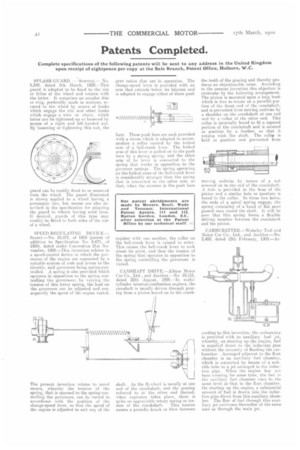
SPLASH-GUARD. — Sturiney.---No. 5,342, dated 5th March, 1909.—This guard is adapted to be fixed to the rim or felloe of the wheel and rotates with the latt-er. It comprises au annular disc or ring, preferably made in sections. secured to the wheel by means of hooks which engage the rim and other hooks which engage a wire or chain, which litter can he tightened up or loosened by means of a right and left-handed nut. By loosening or tightening this nut, the guard can be readily fixed to or removed from the wheel. The guard illustrated is shown applied to a wheel having a pneumatic tire, but means are also deseribed iri the specification for adapting the guard to wheels having solid tires. If desired, guards of this type may readily be fitted to both sides of the rite of a, wheel.
SPEED-REGULATING DEVICE.— Saurer.—No. 10,471, of 1909 (patent of addition to Specification No. 6,671, of 1009), dated under Convention 21st November, 1908.—This invention relates to a speed-control device in which the governors of the engine are connected by a uitablo system of rods and levers to the throttle, said governors being spring-controlled. A spring is also provided which operates in opposition to the spring eontrolling the governors; by varying the tension of this latter spring, the load on the governors can be adjusted and consequently the speed of the engine varied.
The present invention relates to novel means, whereby the tension of the spring, that is opposed to the spring controlling the governors, can be varied in accordance with the position of the change-speed lever, so that the speed of the engine is adjusted to snit any of the
gear ratios that are in operation. The change-speed lever is provided with an arm that extends below its fulcrum and is adapted to engage either of three push bars. These push bars are each provided with a recess which is adapted to accommodate a roller carried by the forked arm of a bell-crank lever. The forked arm of this lever is pulled on to the push bars by a strong spring, and the other arm of he lever is corinected to the spring that works hi opposition to the governor springs. The spring operating on the forked arms of the bell-crank lever is considerably stronger than the spring that is connected to the other arm, so that, when the recesses in the push bars register with one another, the roller on the bell-crank lever is caused to enter. This causes the bell-crank lever to rock about its pivot, and thus the tension of the spring that operates in opposition to the spring controlling the governors is varied.
CAMSHAFT DRIVE.—Albion Motor Car Co., Ltd., and Another.—No 19,151, dated 20th August, 1909.—In cylinder internal-combustion engines, the camshaft is usually driven through gearing from a pinion keyed on to the crank ahaft. As the flywheel is usually at one end of the crankshaft, and the gearing referred to at the other end thereof, when explosion takes place, there is quite an appreciable rotary spring or tor
sion of the crankshaft. This torsion causes a periodic knock or blow between the teeth of the gearing and thereby produces an objectionable noise. According to the present. invention this objection is overcome by the following arrangement. The pinion is mounted upon a long hush which is free to rotate on a parallel portion of the front end of the crankshaft, and is prevented from moving endwise by a shoulder on the crankshaft at one end and by a collar at the other end. This collar is internally bored to fit a tapered portion of the crankshaft and is secured in position by a feather, so that it rotates with the shaft. The collar is held in position and prevented from moving endwise by means of a nut screwed on to the end of the crankshaft. A hole is provided in the boss of the pinion and a similar hole or aperture is bored in the collar. In these two holes, the ends of a spiral spring engage, the spring consisting of a band of flat steel passed once round the shaft. It will be seen that this spring forms a flexible driving member between the crankshaft and the pinion.
CARBURETTER.—Wolseley Tool and Motor Car Cu., Ltd., and Another.—No. 3,453, dated 12th February, 1009.—Ac
carding to this invention, the carburetter is provided with an auxiliary fuel jet, whereby, on starting up the engine, fuel is supplied direct to the induction pipe without the necessity of flooding the carburetter. Arranged adjacent to the float chamber is an auxiliary fuel chamber, which is connected by means el a suitable tube to a jet arranged M. the induction pipe. When the engine has not been running for some time, the fuel in the auxiliary fuel chamber rises to the same level as that in the float chamber. Ort starting up the engine, a substantial amount of fuel is drawn into the induction pipe.direet from this auxiliary chamber. The flow of fuel through this auxiliary jet continues thereafter at the same rate as through the main jet.