


Heat-controlled Fan
Page 82
If you've noticed an error in this article please click here to report it so we can fix it.
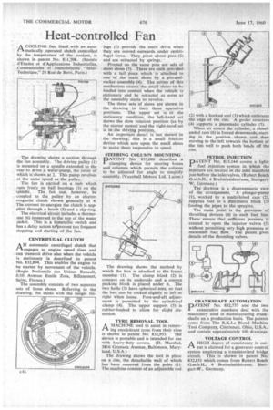
A COOLING fan, fitted with an auto
matically operated clutch controlled by the temperature of the coolant, is shown in patent No. 831,708. (Societe d'Etudes et d'Applications Industriclies, Commerciales et Inunobilieres " InterTechnique," 29 Rue de Berri, Paris.) The drawing shows a section through the fan assembly. The driving pulley (1) is mounted on a spindle extended to the rear to drive a water-pump, the rotor of which is shown at 2. This pump revolves at the same speed as the pulley.
The fan is carried on •a hub which runs freely on ball bearings (3) on the spindle. The fan can, however, be coupled to the pulley by an electromagnetic clutch shown generally at 4. The current to energize the clutch is supplied through a brush (5) and a slip-ring.
The electrical circuit includes a thermostat (6) immersed in the top of the water jacket. This is a bimetallic switch and has a delay action to‘prevent too frequent stopping and starting of the fan.
CENTRIFUGAL CLUTCH
A N automatic centrifugal clutch that AN
as engine speed rises and can transmit drive also when the vehicle is stationary is described in patent No. 832,894. This enables the engine to be started by movement of the vehicle. (Regie Nationale des Usines Renault, 8/10 Avenue Emile Zola, Billancourt, Seine, France.)
The assembly consists of two separate sets of three shoes. Referring to the drawing, the shoes with the longer lin
ings (1) provide the main drive when they are moved outwards under centrifugal force. They pivot about pins (2) and are retracted by springs.
Pivoted on the same pins are sets, of short shoes (3). These are each provided with a tall piece which is attached to one of the main shoes by a pin-androcker assembly (4). The action of this mechanism causes the small shoes to he loaded into contact when the vehicle is stationary and be retracted as soon as the assembly starts to revolve.
The three sets of shoes are shown in the drawing in their three operative positions. • The upper set is in the stationary condition, the left-hand set shows the slow rotation position (as by the starter motor) and the right-hand set is in the driving position.
An important detail is not shown in the drawing; this is a small friction device which acts upon the small shoes to make them responsive to speed.
STEERING COLUMN MOUNTING DATENT No. 833,086 describes a clamping device for steering boxes and columns which permits the column to be adjusted for angle to simplify assembly. (Vauxhall Motors, Ltd., Luton:)'
The drawing shows the method by which the box is attached to the frame member (I). The clamp Mock (2) is concave on its underside and a convex packing block is placed under it. The two bolts (3) have spherical nuts, so that the box can be rocked slightly to left or right when loose. Fore-and-aft adjustment is permitted by the cylindrical clamp (4). The upper support (5) is rubber-bushed to allow for slight distortion.
TYRE REMOVAL TOOL
A MACHINE tool to assist in removing recalcitrant tyres from their rims
is shown in patent No. 832,953. The device is portable and is intended for use with heavy-duty covers. (D. Marshal, 3816 Granada Avenue, Baltimore, Maryland, U.S.A.) The drawing shows the tool in place on a rim, the detachable wall of which has been removed from the point (1). The machine consists of an adjustable rod (2) with a hooked end (3) which embraces the edge of the rim. A girder structure (4) supports a pneumatic cylinder (5).
When air enters the cylinder, a chiselended ram (6) is forced downwards, starting in the position shown and then moving to the left towards the bottom of the rim well to push both beads off the rim.
PETROL INJECTION
PATENT No. 833,144 covers a lightfuel injection 'system in which the . injectors are located in the inlet manifold just before the inlet valves. (Robert Bosch G.m.b.H., 4 Breitscheidestrasse, Stuttgart
W, Germany.) " • The drawing is a diagrammatic view of the arrangement. A plunger-pump (1), worked by it multi-lobed cam (2), supplies fuel to a distributor block (3) feeding the pipes to the sprayers.
The main point is the provision of throttling devices (4) in each fuel line. These ensure that sufficient pressure is created to open the injector valves (5) without permitting very high pressures at maximum fuel flow. The patent gives details of the throttling valves.
CRANKSHAFT AUTOMATION
PATENT No. 832,757 and the two consecutive numbers deal with the machinery used in .manufacturing crankshafts on a production basis. The patents come from The R.K.Le Blond Machine Tool Company, Cincinnati, Ohio, U.S.A., and contain approximately 100 drawings.
VOLTAGE CONTROL
A HIGH degree of consistency in out1"/ put is claimed for a generator control system employing a transistorized bridge circuit. This is shown in patent No. 832,851 which comes from Robert Bosch G.m.b.H., 4 Breitscheidstrasse, Stuttgart-W., Germany.