


External Combustion in New Piston Engine
Page 72
Page 73
If you've noticed an error in this article please click here to report it so we can fix it.
General Motors Revive. the Stirling External combustion engine Design Originated in 1816: Wide Fuel Range and Quiet Operation
IN any piston-type internal-combustion engine, burning of the fuel charge around top dead centre causes the pressure of the gas to increase and this creates a useful force on the piston. If the cylinder were filled with highly compressed cooled air without fuel at top dead centre, and air temperature were increased by transferring heat from an external source to the "combustion chamber," the air would expand and produce useful energy in an operation similar to that of a conventional internal-combustion engine.
If the temperature of the working air could be reduced sufficiently on the upward or compression stroke of the piston, the cycle could then be repeated without loss of working air.
This briefly • describes the basic principle of the Stirling engine cycle, evolved in 1816 and recently applied by General Motors research laboratories to single-cylindered and multi-cylindered power units. Details of the system and its practical application are outlined in the April Journal of the Society of Automotive Engineers by Gregory Flynn, jnr., Worth H. Percival, and F. Earl Heffner.
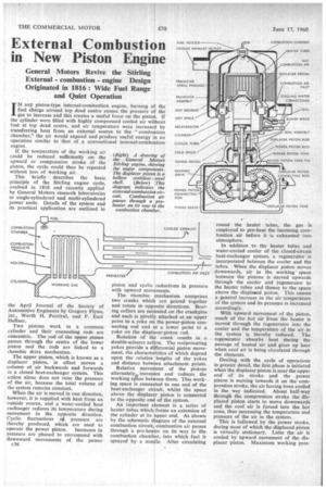
Two pistons work in a common cylinder and their connecting rods are concentric. The rod of the upper piston passes through the centre of the lower piston and the rods are linked to a rhombic drive mechanism.
The upper piston, which is known as a displacer piston, in effect moves a column of air backwards and forwards in a closed heat-exchanger system. This action alone does not raise the pressure of the air, because the total volume of the system remains constant.
When the air is moved in one direction, however, it is supplied with heat from an outside source, and a water-cooled heat exchanger reduces its temperature during movement in the opposite direction. Cyclic fluctuations og, pressure are thereby produced, which are used to operate the power piston. Increases in pressure are phased to correspond with downward movements of the power c36 piston and cyclic reductions in pressure with upward movements.
The rhombic mechanism comprises two cranks which are geared together and rotate in opposite directions. Bearing collars are mounted on the crankpins and each is pivotly attached at an upper point to a yoke on the power-piston connecting rod and at a lower point to a, yoke on the displacer-piston rod.
Rotation of the crank results in a double-scissors action. The reciprocating yokes provide a differential piston movement, the characteristics of which depend upon the relative lengths of the yokes and distance between attachment points.
Relative movement of the pistons alternately., increases and reduces the working space between them. This working space is connected to one end of the heat-exchanger circuit, whilst the space above the displacer piston is connected to the opposite end of the system.
An important element is a series of heater tubes which forms an extension of the cylinder at its upper end. As shown by the schematic diagram of the external combustion circuit, combustion air passes through a pre-heater on its way to the combustion chamber, into which fuel is sprayed by a nozzle. After circulating round the heater tubes, the gas is employed to pre-heat the incoming combustion air before it is exhausted into atmosphere.
In addition to the heater tubes and water-cooled cooler of the closed-circuit heat-exchanger system, a regenerator is incorporated between the cooler and the tubes. When the displacer piston moves downwards, air in the working space between the pistons is moved upwards through the cooler and regenerator to the heater tubes and thence to the space above the displaced piston. This causes a general increase in the air temperature of the system and its pressure is increased accordingly.
With upward movement of the piston, much of the hot air from the heater is moved through the regenerator into the cooler and the temperature of the air in the system is thereby reduced. The regenerator absorbs heat during the passage of heated air and gives up heat when cool air is being circulated through the elements.
Dealing with the cycle of operations in greater detail, the first phase is initiated when the displacer piston is near the upper end of its stroke and the power piston is moving towards it on the compression stroke, the air having been cooled in the way indicated. About half-way through the compression stroke the displaced piston starts to move downwards and the coot air is forced into the hot zone, thus increasing the temperature and pressure of the air in the system.
This is followed by the power stroke, during most of which the displaced piston is virtually stationary. Later the air is cooled by upward movement of the displacer piston. Maximum working ores sores vary between 1,000 psi. and 1,500 p.s.i., according to the size of the unit.
Comprising a stack Of stainless-steel tubes, the heater is brazed to the cylinder head, whilst the regenerator consists of a large number of fine wires located in cups at the base of the heater coils. Forming an annular unit round the upper part of the cylinder, the cooler consists of packs of small tubes mounted in a chamber through which water is circulated.
A hollow stainless-steel shell, without
rings is employed as .a displacer piston. The power piston is "equipped with piston rings to reduce air leakage, and on its lower side is a buffer space, designed to reduce the mechanical loading of the drive mechanism. Seals are provided between the connecting rod of the displacer piston and the power piston, and between the rod and crankcase housing.
Performance curves for the Stirling engine show that its maximum thermal efficiency is below that of a typical oil engine, but is higher than the average effi eiency of petrol engines. Its specific weight and first cost are greater than those of an oil engine, but it has the advantage of smooth operation and is reasonably quiet.
Moreover, the unit can operate on a wide range of fuels and the exhaust gas is free from carbon monoxide. A large radiator is required and it is necessary to employ a blower to force air through the pre-heater to the combustion chamber.