


ACCESSIBILITY IN UNDER / TYPE WAGON DESIGN.
Page 11
Page 12
Page 13
If you've noticed an error in this article please click here to report it so we can fix it.
Full Details of the New 6-ton Mann Steam Wagon, which Embodies a Patented Boiler,Unit Construction of Engine and Gearbox, Bevel and Spur Double, reduction Drive and a Steam-Actuated Brake.
IN DESIGNING their new 6-ton. undertype steam gon, Mann's Patent Steam Cart and .Wagon Co., Ltd., of Pepper Road, Hunslet, Leeds, have had at their backs the accumulated experience of many years of steam wagon constructiem, both undertype and oventype, and for details of what they have already achieved in this direction we cannot do better than refer our readers to the brief history of the company which appeared in our last
issue. .
The new wagon simply bristles with good features, and contains not a few novelties. Accessibility and long life may be said to be the ruling coneiderations, and it has. been the anibition of its progenitors to combine, so far as possible, all that is best in both steam and petrol_ practice, whilst retaining a very satisfactory measure of indi viduality. •
It is the stunted opinion of the makers that the steam vehicle, if it is to make real headway in the future, must offer the advantages of the petrol vehicle together with others of its own; whether they have succeeded in carrying out this ideal only timeand work under arduous conditions of service can show, but from our critical inspection of the Chassis and the detail drawings, we consider that a real advance bas been made, and one which will probably have far-reaching effects on the success of the steam wagon industry.
For many years we have strongly advocated the building of steam vehicles more on the lines or the aver-age petrol vehicle, for we considered that the older designs had almost outgrown their purpose and that, with higher road speeds and the competition of other types of vehicle, the mere primeval ruggedness of their build was no -longer a valuable asset. Several wagons on much more up-to-date lines have been produced within the past two or three years, and it is probable that others will soon be on the market. We believe that the powerful influence of this journal has contributed in no small measure to this state of affairs.
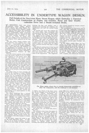
The Mann undertype has a vertical boiler, which outwardly only resembles those employed on several other widertype vehicles, an engine with two ft.P, cylinders, which is suspended under and across the frame, a two-speed gearbox, which is built as a unit with this engine, and final drive by beveland-spur double-reduction gearing. The units are built up on a perfectly straight rolled channel-steel frame with strong cross-members, and it is to be noted that particular care has been taken to prevent weakening the side members by drilling the flanges.. Where spring brackets, etc., have to be fitted, the holes for their bolts are in the web, each bracket being, turned round the lower flange of the side member to which it is fixed.
in the steam wagon the boiler is one
of the most important units. In this ease, it. is of -novel construction, comprising an outer shell, an inner member
forming the flue and firebox, and a domed cover carrying the chimney, the superheater coil and the central firing chute.
To obviate the usual flat surfaces for the water tubes, deep triangular ribs are pressed in the wall of the inner member. in plan, the tubes, when in position, appear as two squares, one turned at 45, degrees across the other, thus giving 16 faces into which the tubes are expanded. The tubes are inclined from the horizontal plane so that they cross in pairs, and the whole surrounds the central chute so closely that the gases must circulate between the tubes to find egress.
The domed construction of the top of the boiler prevents the gases from flowing across the interior of the boiler direct to the chimney. This construction also enables two extra coils to be i used in the superheater. For inspection
sr repair, the whole of the inner member can be dropped from the bottom of the boiler without disturbing any mountings. Fusible plugs are sometimes itserted from the interior, and to renew them it is then necessary to remove the top cover and superheater, but in the Mann boiler this plug is situated opposite a small cover in the outer shell.
The, boiler mountings are all fitted to machined surfaces so that they can be exchanged without hand labour. The usual asbestos fabric joints are employed, but no scraping is necessary. All valves, etc., are fitted with renewable seats.
The exhaust steam from the-engine is taken through a feed-water heater ,of the usual copper-coil type, the intake and, outlet for the water and steam respectively being sa arranged that the water flows in the • direction of the incoming steam. The device also acts as a silencer, and .hy bringing the water almost to boiling point promotes economy and relieves the boiler from un
due stresses caused -by unequal contraction and expansion.
The arrangement of the power unit is such that this undertype construction iEt givensthe same degree of accessibility as the overtype. The two H.P. cylinders have a bore of 5,1 ins, and a stroke of 7 ins., giving a power which is claimed to have achieved the happy medium between the powerful engine employed on. the single-geared. machine and the much smaller type -generally used where several gear changes are . provided.
In the Mann engine there are two points of cut-off. It can climb all normal hills with its 6-ton load at a quarter cut-off, but if in the middle of a long climb there is a hump, the valve timing can be altered to give three-quarter cut-off, thus avoiding the changing of i gears. When used n conjunction with a trailer, the vehicle can iurrnount steep hills at a quarter cut-off and in low gear; it then has the three-quarter cut-off as the equivalent of another emergency gear for exceptionally hard work. The vehicle has been tested with loads of 12 tons, and ha been proved to give the equivalent of a four-speed gearbox without its mechanical cons• plication.
A single steel casting is employed for the crankcase and gearbox, and in this • thireninkshaft is carried in three .Hoffmann roller bearings of extra large size. Two of these bearings support the crankshaft Prosier, whilst the third is accommodatedat the rear end of the, gearbox and .carries the splined portion of the -crankshaft upon which run the two
sliding gears. '
A very large inspection cover is provided atqlsesoffside of the engine, and this gives ready access to the big-ends and also to the main water-feed pump.
The valves are of the poppet type, operated by two camshafts, one for the inlet and the other -for the exhaust. Each camshaft is mounted in a casing carried between the cylinders, cast aluminium extensions being fitted between these casings and the crankcase. The camshafts are driven from the crankshaft through the medium of a spiral pinion ou the crankshaft which meshes with the two driving wheels. The last-named are connected to the camshafts through the medium of two driving shafts, and the joint between each camshaft and its driving shaft takes the form of a split coupling, one of the bolts of which meshes with worm teeth cut in the driving shaft, thus providing a satisfactory form of adjustment which can be securely locked as required.
All the valves are completely accessible from the near side of the vehicle, as are also the main glands, of which two are provided, to prevent water gaining access to the crankcase. The benefit of fitting the exhaust valves at the bottom is that, by putting the camshafts into the neutral position and opening the steam valve, any water in the cylinders is blown out of the exhaust. The valve Beatings and guides are renewable, and adjustable tappets are utilized, thus following and, in sonse respects, improving upon, the best motor practice.
There is a grOove in each camshaft driving shaft in which engages one of the two levers by which the camshafts are shifted bodily to give the reverse, and the two points of out-off. To provide for this movement there are 12 cams on the inlet camshaft and eight on the exhaust, but as certain of the cams have. to be duplicated the actual number of different profiles is six and lour respectively. Die-cast white-metal bearings are employed for the big-ends, and each bigend has a dipper with a direct duct leading into the bearings.
The lubricant, is carried in the crankchamber, and any excess thrown up by the big-ends is caught in two trays, which are cast with the casing, at the -forward end and directly under oath of the camshaft driving shafts. The oil thus caught runs along the aluminium extensions, previously referred to, to a sump underneath the cams, thus giving putomatic lubrication to all parts. The leeel of the oil in these trays is regulated by the height of the walls,. which, can be built up or reduced if required.
The cylinders themselves are separate and interchangeable. This also applies to the camshaft housings, so that if any one part is damaged it can be replaced at small cost and With despatch.
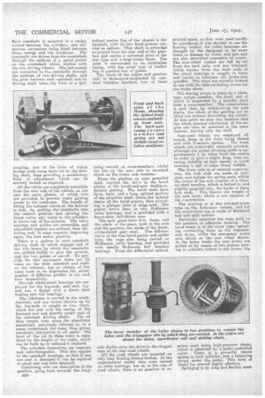
Continuing with our description of the gearbox, going ha& towards the IongiB28 tudinal centre line of the chassis is the layshaft, with its two fixed pinions carried on splines. This shaft is extended to project from the rear end of the gearbox and carries a universal joint of the star type and a large brake drum. The joint is surrounded by an aluminium casing, with the usual type of leather bag to prevent loss of grease. The whole bf the engine and gearbox unit is three-point-suspended by caststeel trunnion brackets, two of these being carried on cross-members, whilst the one an the near Bide is mounted direct on the frame side member.• Frain the gearbox an open propeller shaft conveys the drive to the bevel pinion of the bevel-and-spur double-reduction gearing. The bevel teeth have 3i-in. faces, and a long, splined portion of the propeller Shaft enters the splined sleeve of the bevel pinion, thus providing a plunger joint of large .area. The pinion sleeve runs in two Hoffmann roller bearings, and is provided with a heavy-duty ball-thrust race. The spur gears have 4-in, faces, and the whole of the gears, both in the axle and the gearbox, are made of the finest, oil-hardened gear steel. The differential is of the four-bevel-pinion and spider type, the cage also being carried on Hoffmann roller bearings and provided with spectal Hoffmann ball location bearings. From the differential splined axle shafts carry the drive to the dogged caps of the rear road wheels. All the road wheels are mounted on very long floating brims° bushes. In the experimental model they were carried on roller bearings, but as, in the case of road wheels, there is no question of re stricted space, so that wear need hardly be considered, it was decided to use the floating bushes, fur roller bearings are thought by the designees to be more liable to damage by water and grit and are also Scenewhat expensive to renew. The rear-wheel bushes are fed by oil from the back axle, and any lubricant which exudes from, the inner ends of the wheel bearings is caught in trays, and 'serVes tO lubricate the brake-cam spindles. The trays are actually formed in one with the dust-exchiding covers for the brake shoes.
The driving torque is taken by a platetype torque \member, the front end of which is suspended by a knuckle joint from a cross-member. The construction is such that, by -withdrawing the axle shafts, the whole of the gearing can be lifted out without disturbing the wheels. At this point we may also mention that the whole internal mechanism el the engine can -also be removed in the same manner, leaving only the shell.
Cast-steel wheels are employed all round, those at the front being dished and with T-section spokes.• The front wheels are practically centrally pivoted, although the actual pivoting point is approximately.1 in. away from the centre in order, togiv6 a slight drag, thus en, suring stabitity at high speeds, as exact centring is apt to cause wheel wobble.
The front axle is of unusual construction, the fork ends are made of caststeel, and include the spring seats, whilst the centre of the axle consists of a channel-steel member, which is bolted to and slightly spigoted into, the backs of these fork ends. This throws the weight of the axle back, which is one purpose of the construction.
The steering is of the nut-and-worm 'type on the Ackerman system, and for the connections use is made of Kirkatall ball and split sockets.
Particular attention has been paid to the question of adequate braking. The hand brake is of the screw type operating contracting shoes on the tiansmission dr mm, whilst the emergency brake acts direct on the rear .wheel drums. In the latter brake the cam levers are pulled on by means of two pistons rimying in cylinders bolted to the frame, the power used being high-pressure steam, which is admitted by a pedal-controlled valve. There is a powerful return spring in each cylinder, and a balancing spring under the pedal. This form of brake ha .s proved highly effective.
Springing-is by long and flexible semi
ellipties at each end, the rear ends of the springs working in slippers. The control has been designed on the lines of the standard private car, changespeed and cut-off levers being placed at the rignt, the steam being controlled bv a bend throttle for slow running, whilst the main throttle it by an accelerator pedal operated by the right' foot. These steam controls are on separate pipes, and each acts as a „safeguard for the other.
The water tank is carried longitudinally at the back of the frame, the supply being by injector and pump, and it holds sufficient for from 30 miles to 35 miles. The cab has a seat at each side with the fuel bunker between; this holds sufficient for 100 miles' running. The water from the tank is taken off by two independent pipes, one for the pump and the other for the injector. Each of these pipe-lines is provided with a: strainer ad the tank end, and a cock permits each strainer to be cleaned without difficulty while the•tank is full.
A neat method is employed to prevent, so far US possible, the stranding of a wagon Orough lack of water ; this is effected be carrying the injector supply
pipe to the bottom of the tank, and some little way below the pipe for the pump; thus, when the pump supplY gives out there is still sufficient, water in the tank to keep the. injector working fOr three or four miles.
Surging of the water in the tank is prevented by the fitting of baffle plates, and the tank itself is prevented from Moving in the straps, by which it is supported from two cross-members, by the use of wood packing between the tank and frame.
Owing to the shaft drive being to one side of the chassis, ample space is left for the cylinder of the tipping, gear, which will be of the oil type with a separate pump. The leading dimensions of the Mann utclertype are :—Overall length, 21 ft. 3 ins.; width, 7 ft. 4 ins.; wheelbase,11 ft. 5 ins. ; body, 15 ft. 6 ins. by 7 ft. ; loadinw rilatiorm, 4 ft. from .
giound. Tyres sizes i--Twin 160 mm.
by 850 mm. fitting' at the rear, and 180 mm. by 771 main fitting at the front. The unladen weight is approarnately 6 tons, and speeds up to 25 m.p.h. can be obtained. Two gear ratios are provided, these being 5.3 to 1 and 8.6 to 1.
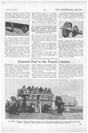
2 The only photograph of a complete vehicle which is at present available shows the experimental model and not those under construction, and limitations of space have prevented our using this and certain drawings, which we shall include in our next issue.