


Patents Completed.
Page 22
If you've noticed an error in this article please click here to report it so we can fix it.
Warrick Safety Lock for Parcelcars. Pneumatic Shock Absorber. RolIs-, Royce Engine Mounting.
Copies of complete specifications of the patents published on this page can be obtained from the Sales Branch, Patent Office, Holborn, W.C., at the cost of sixpence for each specification.
.1, Waimea, No, 557, dated 13th Jitnuary, 1915.—According to this specification the foot brake is used to provide a safety lock for motor •vehicles to prevent unauthorized tampering with them. The quadrant of the foot brake is pro
vided with ratchet teeth on its front edge to engage one edge of a slot in a plate fixed on the floor of the vehicle. NorMany there is sufficient space in the slot for the rack to operate freely, but when the vehicle is to be left the brake is applied and the quadrant locked with its teeth engaging the edge of the •plate. The lucking is Affected by a bolt which is entered behind the quadrant to force it forward, the bolt being operated through a bell-crank lever and tie.rod from inside the body of the vehicle.
When the driver is delivering goods, he locks the vehicle at the. same time as he is removing the goods from the in tenor and shuts the door, which preferably has a spring lock,
SO that it is impossible to set the vehicle in motion. .
• W. P. Brtanstraw, No. 11,519, dated 9th May, 1914.—This specification describes a mOtor vehicle in which an individual drive is given to each of the four wheels by a small steam turbine driving through a worm gear, a small pinion meshing with an internal gear on the road wheel. The axle for each pair of road wheels is fixed, and is mounted on a turntable under the vehicle, and the steering is effected by right and left-hand worms on a single shaft connected to the steering column, and operating on the turn-tables. The boiler supplies steam through flexible tubing to the turbines, which are seen in the plan view, adjacent to each axle, and the exhaust is conducted by other flexible tubes to a condenser underneath the middle of the vehicle,
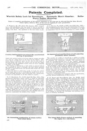
E. B. KILLEN, No. 24,063, of 1913, dated 23rd May, 1914.— The accompanying drawing shows one construction of a pneumatic shock-absorbing device .which is -intended to be • used in conjunction with-the laminated springs on a motor vehicle.
The annular air cushion is formed by a rubber or rubber and canvas casing attached to a base-plate under such pressure as maintains the connection airtignt. The attachment is made by inwardly-directed toes on. the cushion engaging grooves in the base-plate, and outwardly-directed heels which are held by a hook-shaped ring to the base-plate. This pneumatic cushion may be applied either at the ends or at the middle of the laminated springs and preferably the latter are weakened by removing one or two leaves. It is stated that with this arrangement springs can be made equally sensitive for light or heavy loads, and therefore overcomes the difficulty. which is experienced with the ordinary type of laminated spring.
Numerous illustrations are included with the specification, showing various modifications of this invention.
F. H. ROYCE and Roi,ns-RoYeE, LTD., No. 22,993, dated 24th November, 1914.—According to this invention the engine and gearbox, or either one of them, are mounted on a subframe forming with it, a complete unit. This frame is mounted in trunnions in the main frame, the trunnions being preferably co-axial with the engine shaft. Swinging movement of the sub-frame is controlled bya spring connection between side brackets on it and the main frame. Springs are used above and below the bracket, the lower springs, of course, being much stiffer, because they have to take part of the weight of the engine. A friction-damping device is mounted in front of the engine to prevent the sub-frame from getting into a state of vibratory oscillation.