


A SECOND STAIRCASE IN A DOUBLE-DECK BUS.
Page 68
If you've noticed an error in this article please click here to report it so we can fix it.
A Rdsurrid of Recently POlished Patent Specifications.
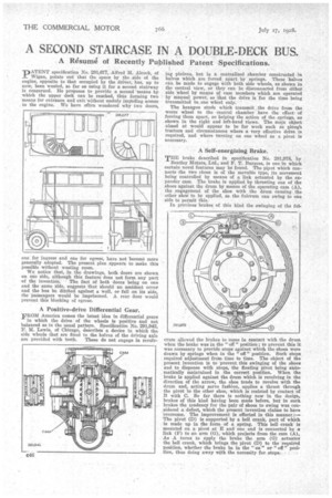
"DATENT specification No. 291,677, Alfred M. Alcock, of
Wigan, points out that the space by the side of the engine, opposite to that occupied by the driver, has, up to now, been wasted, so far as using it for a second stairway is concerned. He proposes to provide a second means by which the upper deck can be reached, thus forming two means for entrance and exit without unduly impeding access to the engine. We have often wondered why two doors,
one for ingress and one for egress, have not become more generally adopted. The present plan appears to make this Possible without wasting room.
We notice that, in the drawings, both doors are shown on one side, although this feature does not form any part of the invention. • The fact of both doors being on one and the same side, suggests that should an accident occur and the bus be ditched against a wall, or fall on its side, the passengers would be imprisoned. A rear door would prevent this blocking of egress.
A Positive-drive Differential Gear.
FROM America comes the latest idea in differential gears
in which the drive of the wheels is positive and not balanced as in the usual pattern. Specificatien No. 291,942, F. M. Lewis, of Chicago, describes a device in which the side wheels that are fixed to the halves of the driving axle are provided with teeth. These do not engage in revolv
lag pinions, but in a centralized chamber constructed in halves which are forced. apart by springs. These halves can be made to engage with both side wheels, as shown in the central view, or they can be disconnected from either side wheel by means of cam members which are operated by manual power, so that the drive is for the time being transmitted to.one wheel only. '
The hexagon studs which transmit the drive from the worm wheel to thefl central chamber have the effect, of forcing them apart, so helping the action of the springs, as shown in the right and left-hand views. The main object aimed at would appear to be for work such as plough tractors and circumstances where a very effective drive is required, and where turning on one wheel as a pivot is necessary.
A Self-energizing Brake.
TDB brake described in specification No. 291,978, by
Bentley Motors, Ltd., and P. T. Burgess, is one in which certain novel features may be found. The piyot which connects the two shoes is of the movable type, its movement being controlled by means of a link actuated by the expander cam. The brake is applied by thrusting one of the shoes against the drum by means of the operating cam (A), the engagement of the shoe with the drum causing the other shoe to he applied, as the fulcrum can swing to one side to permit this.
In previous brakes of this kind the swinging of the ful
crum allowed the brakes to come in contact with the drum when the brake was in the " off " position ; to prevent this it was necessary to provide stops against which the shoes were drawn by springs when in the " off " position. Such stops required adjustment from time to time. The object of the present invention is to prevent this swinging of the shoes and to dispense with stops, the floating pivot being automatically maintained in the correct position. When the brake is applied against the drum which is revolving in the direction of the arrow, the shoe tends to revolve with the drum and, acting servo fashion, applies a thrust through the pivot to the other shoe, which is resisted by contact of B with C. So far there is nothing new in the design, brakes of this kind having been made before, but in such brakes the tendency for the pair of shoes to swing was considered a defect, which the present invention claims to have overcome. The improvement is effected in this manner,:— The pivot (D) is supported by a bell crank, part of which is made up in the form of a spring. This bell crank is mounted on a pivot at E and one end is connected by a link (r) to an arm (G), which projects from the cam (A), As A turns to apply the brake the arm (G) actuates the bell crank, which brings the pivot (D) to the -required position, whether the brake be in the " on " or " off " position, thus doing away with the necessity for stops.