


REPAIR-SHOP EQUIPMENT.
Page 27
If you've noticed an error in this article please click here to report it so we can fix it.
Valuable Advice from Our Driver and Mechanic Readers. '
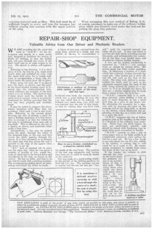
WE ARE awarding the 15s. prize' this week to " G.D.W." for his description and sketch of a most useful tool, designed to facilitate the setting of shafts for drilling, so that the drilled hole. will pass through the centre of the shaft itself and be at right angles to its axis. Ifis sketch is almost self-explanae tory.
.Referring to the drawing, A is a short piece of 2-m. by 2-in by h-in. angle steel neatly filed and polished all over, with the angle filed away for a length suffieient to accoresmoslate a brass clip (c), which holds the spirit level (B) in plane.
When using the tool, the V is placed over the shaft, as shown, and the point Of the knurl-headed locating screw is inserted into the centre-punched hole, which indiCates the location of the bole which is to be drilled. The shaft is then twisted about until the bubble in the spirit level is central, when it is correctly positioned for drilling -provided that the tool has been properly and carefully made.
It may be useful to compare the above simple operation with those that are necessary when such a tool is not available. Referring to the second sketch thewing one way of Setting a shaft for i
such a drilling operation, it s first necesSnry to arrange it so that. the oentne for the bole is equidistant from each side of thess-haft. This is effected by the use of a square, as shown, and sometimes takes quite a long time.
Alternatively, a line may be scribed along the shaft, through the centre of the proposed hole, to the end, and then across the shaft, passing through the centre. It is then necessary so to arrange the shaft that this line across the end_ is parallel to the edge of the square when the latter is set up.
" E.J." had an unusual job to carry out the otherday, when he was given a number of lengths of sit-in. round bar, each of which had to be turned down and shouldered at the end, as shown in the sketch. Re has no lathe, and had to do the best he could with a drilling machine. The accompanying sketch shows an interesting and simple jig which he made.
A block of cast-iron, selected from the scrap heap, served as a stand, and wa$ drilled, as shown, to accommodate a
hardened steel bush, the central hole in which was a good eliding fit over the hsin. bar which, had to be reduced. A
suitahle -tool made from drill rod was insetted into the side of this block, so that its cuttifig edge was level wit the inside of the steel bush: The position of. the tool was adjustable and, having once been set, it could be fixed by means of the setscrew.
Use was made of a quick-acting chuck, in the spindle of the drillingmachine, to hold the kin. bar. The machine was-set in motion and the has fed into the "box mill" until the required amount was taken oil the end. A stop was fitted to prevent the drill chuck travelling beyond this point, and subsequently the remainder of the bars were turned down and shouldered without further trouble.
A new use for broken crankshafts issuggested by "J.R,N.," who employs them as stands for ratchet drills. His sketch needs but little verbal amplification. It illustrates a portion of a shaft which has evidently broken through the crank pin. The broken pin is sawn off, and the web used as the base a the stand. The other web, drilled to accommodate the shaft, may be used as the adjustable support from the buck of the drill, being located by means of a set 'screw or, if -it be thought too heavy for that use, a similar support may be made from a piece of 1i-in bar. • "II.A.B." remarks that it is .work shop practice, when drilling a hale of aP-in, or more diameter, to use a small drill first, as a pilot to the larger one. He eliminates the necessity for a separate drill by forming the pilot on the business end of the main drill, as shown on the sketch, which illustrates the application of this idea to a twist drill and to a plain fiat drill.
"A.M.D," suggests the use of hollow gudgeon pins as file handles, in the event of a shortage of the ordinary type occurring. Those from the Ford engine, he says, are particularly suitable' and should be bound with insulating tape to make them more convenient to handle, " W.J.H," reminds us that a slip of -white paper laid on the lathe saddle is of considerable assistance when setting the tool for a new jet). iI ha e a few words to say also about the use of a vice, which, in his opinion, is nothing like so well cared for as it ought to be. He recommends mechanics to refrain from, using the front of the vice as art anvil.
• son is an animus lation of dirt in that hole. When . using those vices which are fitted with quick return action, be sure that action is "off" when tightening up the work in the vice; ot he r wise the jaws may spring open again and the work find its way on to the floor or on to