


EQUIPPING A COACH FOR WIRELESS RECEPTION.
Page 13
Page 14
If you've noticed an error in this article please click here to report it so we can fix it.
The Employment of the Valve as an Amplifier of High-frequency Currents and Low-frequency Currents ; the Difference Explained.
IN the two articles dealing with the equipment of a coach for Wireless reception, which appeared in the issues of The Commercial Motor for June 26th and July 10th, w.e described the use of the threeelectrode valve as a detector of wireless ether waVes, and in the latter of these two articles we showed how its efficiency in this capacity can be enormously increased by the use of reaction. Now, in this last case, the detecting valve does actually amplify the signals received, but this amplification is. due to. regenerative or feed-back action, and is net what we generally mean when we talk of a valve being used as an amplifier.
A valve acting as an amplifier i'S acting strictly as a relay ; that is to say, controlling impulses receiv_ed on its grid are causing similar, though magnified, impulses in its plate circuit, the energy for which is supplied from a local source. Owing to the fact that there are no moving parts—in the ordinary sense of the word—the Valve is a relay of extreme delicacy, and it is possible for it to function perfectly With currents that alternate at speeds far in excess of 2,000,000 cycles per second.
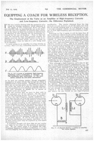
Now the currents that we have 10 .deal with in radio reception are of two natures. On the aerial side of the detecting device—be it valve or crystal-we have the high-frequency, rapidly oscillatory currents that are sent out from the transmitting station, and on the telephone side of the detector we have the positive or negative halves of these currents, which Nary in groups according to the modulation or distortion imposed on them by the speaking voice or the music at the transmitting apparatus, and which, for practical purposes, can be regarded as slow-speed 'or low-frequency alternating currents, exactly similar in their effects to those flowing in an ordinary land telephone circuit. Fig. 0 (a) shows diagranamatically a group of modulated high-frequency oscillations before rectification or detection, and (b) shows the same oscillations after passing through the detecting• or rectifying device. If will he seen that only one half of the oscillations now appear, and these—as far as their action goes—may be replaced by slow-speed alternations (c).
A moment's thought will show that we can employ our valve in two ways for the ,purpose of amplitica. tion. We can either cause it to amplify the highfrequency impulses (a) before rectification, er we can use it to magnify the low-frequency impulses (c) after rectification. The results obtained from the two methods are not, however, at all the sa,ine, but each has its specific p.urpose and, in a receiver for use on a moving transport vehicle, we are obliged to make use of both high-frequency and low-frequency amplification.
Referring to Fig. 6 again, it will be seen that, if the oscillations induced in the aerial circuit are very weak, they may, after rectification, be so minute that they can neither .be heard in the telephone nor be even capable of operating a low-frequency amplifying valve, because, in the process of _rectification, always 50 per cent., and sometimes much more, of the total effective current is lost. But if we amplify them before detection the amplified high-frequency currents may be quite strong enough to be successfully detected and, if necessary, further magnified and, since the, Whole of the original aerial currents are available, without lass, to work our high-frequency valve., this method allows of the reception of much weaker signals than would otherwise be possible. Signal -weakness arises from two causes : distance from the transmitting station and/or a poor aerial. We, therefore, employ high-frequency to compensate these two conditions—in our case, especially the latter, which is unavoidable on a transport vehicle. •
Now, although a high-frequency valve may be giv.;• ing its very greatest possible amplification—i.e., the ratio between the incoming grid currents and the corresponding plate impulses is as high as the design of the valve permits—it does not follow that the amount of current being handled is -very great and, therefore, the volume of sound in the telephones is not necessarily very much increased. If on the other hand, we emplay our valve to amplify the low-frequency speech currents, indicated at (c) in Fig. 4, we shall get an increase in the current available to Operate the 'phones that is exactly proportional to the amplification .factor of the valve and, consequently,. a corresponding increase in the volume of sound in the 'phones. We, therefore, employ low-frequency, or note magnification as it is more often called, whenever we want increased signal strength m cases where we' are already in possession of detectable signals without it. in our transport case, as was pointed out above,we are forced to use high-frequency amplification to compensate for a poor aerial, and we need at least one stage of n.ote magnification to render our signals sufficiently loud to be heard above the inevitable noises on a moving vehicle.
Before going on to the actual circuits employed to allow of valves being used in the two ways described above, we must say a word about the coupling together of two or more valves.
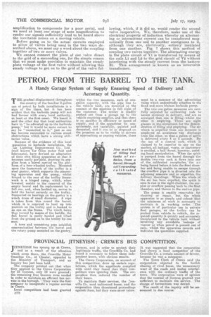
We cannot connect the plate of one valve direct to the grid of a succeeding one, for the simple reason that we must make provision to maintain the steady plate voltage of the first valve without allowing this steady voltage to get on to the grid of the valve fol lowing, which, if it did so, would render the second valve inoperative, We therefore, make use of the electrical property of .induction whereby an alternating or. intermittent current can be transferred magnetically from one coil to another contiguous to it, although they are, electrically, entirely -insulated from one nother. Fig. 7 shows this methOd of coupling two valves together. The alternating energy in the plate eirenit.of VA is transferred by means of the coils Li and L2 -to the grid circuit of V2 without interfering with the steady current from the battery BL This arrangement is known as an intervalve transformer.