


A PROMINENT MA t'S NEW ENGINE.
Page 54
Page 55
Page 56
If you've noticed an error in this article please click here to report it so we can fix it.
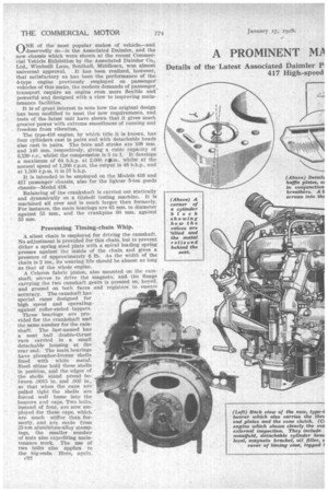
Details of the Latest Associated Daimler 1).
417 High-speed Jnit Designed for the New Models 416 and nger Vehicles.
riNE of the most popular makes of vehicle—and k.ideservedly so—is the Associated Daimler, and the new chassis which were shown at the recent Commercial Vehicle Exhibition by the Associated Daimler Co., Ltd., Windmill Lane, Southall, Middlesex, won almost universal approval. It has been realized, however, that satisfactory as has been the performance of the 4-type engine previously employed on passenger vehicles of this make, the modern demands of passenger transport require an engine even more flexible and powerful and designed with a view to improving maintenance facilities.
It is of great interest to note how the original design has been modified to meet the new requirements, and tests of the latest unit have shown that it gives much greater power with extreme smoothness of running and freedom from vibration.
The type-416 engine, by which title it is known, has four cylinders cast in pairs and with detachable heads also cast in pairs. The bore and stroke are 108 mm. and 140 mm. respectively, giving a cubic capacity of 5,130 c.c., whilst the compression is 5 to 1. It develops a maximum of 64 b.h.p. at 2,000_ rile.tn., whilst at the normal speed of 1,200 r.p.m. the output is 48 b.h.p., and at 1,500 r.p.m. it is 57 b.h.p.
It is intended to be employed on the Models 416 and 417 passenger chassis, also for the lighter 3-ton goods chassis—Model 418.
Balancing of the crankshaft is carried out statically and dynamically on a Gisholt testing machine. It is machined all over and is much larger than formerly. For instance, the main bearings are 65 mm. in diameter against 55 ram., and the crankpins 60 mm. against 55 mm.
Preventing Timing-chain Whip.
A silent chain is employed for driving the camshaft. No adjustment is provided for this chain, but to prevent dither a spring steel plate with a spiral loading spring presses against the inside of the chain and gives a pressure of approximately 6 lb. As the width of the chain is 2 ins., its wearing life should be almost as long as that of the whole engine.
A Celeron fabric pinion, also mounted on the camshaft, serves to drive the magneto, and the flange carrying the two camshaft gears is pressed on, keyed, and ground on both faces and registers to ensure accuracy. The camshaft has special cams designed for high speed and operating against roller-ended tappets.
Three bearings are provided for the crankshaft and the same number for the camshaft. The last-named has a neat ball double-thrust race carried in a small detachable housing at the rear end. The main bearings have phosphor-bronze shells lined with white metal. Steel shims hold these shells in position, and the edges of the shells stand proud between .0015 in. and .002 in., so that when the caps are pulled tight the shells are forced well home into the bearers and caps. Two bolts, instead of four, are now employed for these caps, which are much stiffer than formerly, and are made from 25-ton aluminium-alloy stampings, the smaller number of nuts also expediting maintenance work. The use of two bolts also applies to the big-ends. Here, again,
c3f?. steel shims are employed, but in this case the Duralumin from which the connecting rod is made is carefully tinned, the tinning being well scratched in and white metal cast direct into the red and cap. The process is unusual, but, apparently, very satisfactory, and the white metal makes an intimate joint with the Duralumin. The big-ends are broached and have oil grooves in both halves.
A steel tube, case-hardened, ground and lapped, is employed for the gudgeon pins. These pins are lightly pressed direct into the small ends of the connecting rods and are a good fit in the piston bosses. Aluminium buttons prevent any risk of the pins moving sideways and scoring the cylinder walls. It will be seen that the pins are permitted to float in both pistons and rods. Each connecting rod and piston must weigh within 1, oz. of the others.
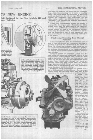
Withdrawing Connecting Rods Through Cylinders.
An interesting feature from the maintenance point of view is that the big-ends are rounded at the sides by grinding, to permit the withdrawal of the piston and whole rod through the cylinders ; both piston and red can also be withdrawn from the bottom of the cylinders. To facilitate this, the inside of the crankcase is belled out slightly at the points where the pistons and rods have to pass.
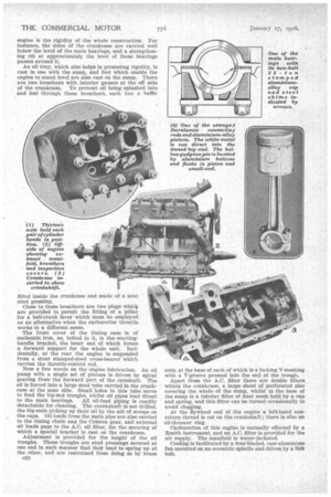
Aluminium pistons are employed. They have flat tops, whilst the sides are ground and relieved in the neighbourhood of the gudgeon pins. There is a wide ring at the bottom of the skirt and three narrow rings at the top, the third ring from the top being of a special scraper type. Small holes through the piston are provided under this ring, whilst other and slightly larger holes are drilled through each piston, the outer orifices being in the centre of a small bevel immediately below the groove for the third ring.
Side-by-side valves are employed ; the exhaust have a lift of 10.5 mm., and the inlet 11 mm. The values are slightly tilted and the metal above each seat at the side nearest the piston is relieved to facilitate the flow of gases. The cylinders are honed, and there are 13 studs on each pair to hold the heads.The faces of both cylinders and heads are ground, and use is made of a copper a n d asbestos gasket. Lifting lugs are provided on the heads, and at the ends of each water jacket are circular plates screwed into position so that the cylinders can, if required, be employed on a s i x cylindered engine.
The combustion chamber is of the turbulent t y p e, and the chamber is offset from the piston centre.
One of the secrets of the vibrationless run ning o f this engine is the rigidity of the whole construction. For instance, the sides of the crankcase are carried well below the level of the main bearings, and a strengthening rib at approximately the level of these bearings passes around it.
An oil tray, which also helps in promoting rigidity, is cast in one with the sump, and feet which enable the engine to stand level are also cast on the sump. There are two breathers with interior gauzes at the off side of the crankcase. To prevent oil being splashed into and lost through these breathers, each has a baffle fitted inside the crankcase and made of a neat steel pressing.
Close to these breathers are two plugs whictL are provided to permit the fitting of a pillar for a bell-crank lever which must be employed as an alternative when the carburetter throttle works in a different sense.
The front cover of the timing case is of malleable iron, as, bolted to it, is the startinghandle bracket, the inner end of which forms a forward support for the whole unit. Incidentally, at the rear the engine is suspended from a stout stamped-steel -cross-bearei which carries the throttle-control rod.
Now a few words on the engine lubrication. An oil pump with a single set of pinions is driven by spiral gearing from the forward part of the camshaft. The oil is forced into a large steel tube carried in the crank case at the near side. Small holes in this tube serve to feed the big-end troughs, whilst oil pipes lead direct to the main bearings. All oil-feed piping is readily detachable for cleaning. The crankshaft is not drilled, the big-ends picking up their oil by the aid of scoops on the caps. Oil leads from the main pipe are also carried to the timing chain and the Celeron gear, and external oil leads pass to the A.C. oil filter, for the securing of which a special bracket is east on the crankcase.
Adjustment is provided for the height of the oil troughs. These troughs are steel pressings secured at one end in such manner that they tend to spring up at the other, and are restrained from doing so by brass
c34 nuts, at the base of each of which is a locking V-meshing with a V-groove pressed into the end of the trough.
Apart from the A.C. filter there are double filters within the crankcase, a large sheet of perforated zinc covering the whole of the sump, whilst in the base of the sump is a tubular filter of finer mesh held by a cap and spring, and this filter can be turned occasionally to avoid clogging.
At the flywheel end of the engine a left-band nonreturn thread is cut on the crankshaft ; there is also an oil-thrower ring.
Carburation of this engine is normally effected by a Zenith instrument, and an A.C. filter is provided for the air supply. The manifold is water-jacketed.
Cooling is facilitated by a four-Bladed, cast-aluminium fan mounted on an eccentric spindle and driven by a link belt.