


PATENTS SUMMARIZED,
Page 24
If you've noticed an error in this article please click here to report it so we can fix it.
A Dunlop Tyre Protector.
In a patent specification (No. 111,682) the Dunlop Rubber Co. describe a wheel guard which is designed to protect the tyre from scraping along the edge of the kerb. It takes the form of a flange which is carried round the rim or felinc of the wheel, and which is inclined outwards at an angle of about 45 degrees. This flange so disposed will strike the kerb or any other similar obstruction before the tyre, and, will prevent the wheel from approaching more closely to tho 'obstruction unless the vehicle is actually directedtowards it.
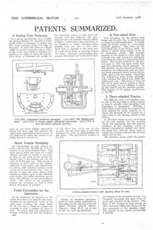
Motor Vehicle Springing.
An arrangement of road springs for motor vehicles (No. 111,705, by A. J. L. Lassen)" is on quits-..unusual lines. The maim springtakes .the form of a halfelliptic, one-half of which is -inverted, so that on one part of the spring the longest leaf is the bottom one ; on the other it is the top one. This spring is shackled at both ends to the chassis. Attached to its centre, and underneath, is a short, stiff cantilever spring; which carries at its free end the axle. The intention is that the main spring shall operate to subdue most of the ordinary road shocks, the stiffer cantilever spring being Only affected by an extraordinary .shock. The leaves of the cantilever springs are arranged so that a little lateral movement is possible.
Pedal Extremities for the Agrimotor.
In an endeavour to improve on t-he wheel as a means of support and transmission for an agrimotor, while at the same time avoiding the chain track, W. H.Nix uses a wheel as a basis and provides it with a number of shoes or feet. He claims that this construction, besides reducing slip and the tendency 1354
for travelling wheels to sink into soft ground, will also eliminate the cornpressive effect of ordinary wheels; afford
a lighter construction; also that there is no bumping or undue vibration, when passing from one foot to ‘the-, next. Each foot is attached, co the outer end of a rod which slide's it hearings within the wheel. Enclosed compensating gear ensures that eatial load is carried by each of the three feet which are on the ground, and also that upon a new foot reaching the earth it accommodates its fair share. Tho specification number is 111,713.
A Two-speed Gear.
This invention, by the Jandus Ard Lamp and Electric Co., is described as an improved differential gear. It would really be better named as a two-speed epicyclie gearbox. The shaft on the • right-hand side is the driving shaft. It carries a hollow drum within which is an expanding clutch. The internal member of the clutch is wider than the _external one, and . retina, the additional space thus provided is a contracting band brake. The normal position of the Tontrol gear 'is 'with the band brake free and the expanding 'clutch engaged. In this 'position, as the expanding.cluteb is pinned to the differential case, the driving shaft transmits direct to the driven shaft, giving the tap speed. Operating the contracting hand brake automatically releases the clutch 'and holds the differential case. The d2ive is thus via the set of gears shown, giving a reduction according to the number of teeth on the wheels and the satellite pinions. The number of the patent specification is 111,752.
A Three-wheeled Tractor.
The difficulty with a two-wheeled tractor lies in the. fact that it needs a trailer to keep it upright when travelling from implement to implement. Putting a fhird wheel in the front as a support has been adopted by many makers, as it alloWs the drawbar to be coupled to a _ pRint close to the driving wheels Of the tractor.
A. Bloxham claims several advantages for the rear position. for. the steering, wheel, but principally that theoppbsed reactions of the draWbar' which is hitched immediately behind and below the -main' axle, and the drive, tend to steady the pressure between the steering wheel and ground..
The drawbar, about which the prinCi
pal interest of the invention centres, is a triangular structure, the apex being in front and attached to the tractor. The base of the triangle is long enough to allow clearance within the framework for free mevement of the steering wheel. The number of the patent specification' "is 111,392.