


For DRIVERS, MECHANICS & FOREMEN • A PRIZE OF TEN
Page 23
If you've noticed an error in this article please click here to report it so we can fix it.
SHILLINGS is awarded each week to the sender of the best letter which we publish on this page ; all others are paid for at the rate of a penny a lane, with an allowance for photographs. All notes are edited before being published. Mention your employer's name, in confidence, as evidence of good faith, Address, D., M. and F„, "The Commercial Motor," 7-15, Rosebery Avenue, London, E.G. 1. .
Lamps Alight—
Light your lamps at 4,58 in London, 5.21 in Edinburgh, 4.49 in Newcastle, 5.2 in Liverpool, 5.2 in Birmingham, 5,9 in Bristol, and 5.45 in Dublin.
Adapting a Lathe for Use as a Cylinder Grinder.
The sender of the following communication has been awarded the 10s. prize this week.
[1819] " U.M." (West Bromwich) writes :—" Improvisation of machines and tools is an importantand essential part of the duties of the garage mechanic. There are many types of machine, extremely useful at times, but for which there is not sufficient work to ensure that they are at all times usefully employed.
"A typical tool of this kind is the cylinder-grinding machine. It would be invaluable in a garage, occasionally perhaps once a week, but as it-is an expensive tool the garage manager usually does without. As a rules an old lathe can, be adapted for the purpose, and the accompanying sketches [which we have had re-drawn.—En.] illustrate midi a conversion.
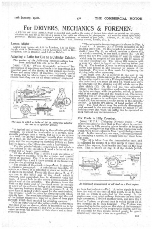
"For the grinder which I constructed, and which is the subject of the sketches, I used a lathe of 26 in. swing and of heavy construction. "Of the sketches Fig. 1 shows a side elevation of the complete machine with the cylinder and special chuck in position. Fig. 2 is an end elevation of the chuck, and Figs. 3 and 4 show details of the traversing gear for the grinding head. " The design of the chuck is impoilant. It deserves a separate paragraph. A substantial faceplate (S) aerves as a base ; it is adapted to screw on to the end of the lathe mandrel. From this three staves (A, A, A) are run to the outer end of the chuck, which is circular, and somewhat less in diameter than the base. A bored hole in the centre accommodates the spigot end of the cylinder. The distance from the base to the outer end of the chuck must be enough to allow of the cylinder being slid into place through the opening between them, and the staves (A, A, A) must also be spaced widely apart for the same reason. The cylinder is held in place by clamping bolts which grip its base. Between the cylinder head and the end of the hollow mandrel is inserted a piece of hose pipe through which dust created by grinding escapes.
"On the outer end of the lathe spindle is secured a cast-iron drum or sleeve, whieh is machined so as to forth_ two driving pulleys (T and T1) • a pipe communicates between the interior of this sleeve and a dustcollecting pipe. "The automatic traversing gear is shown in Figs. 1, 3 and 4. A bracket (A) is loosely. mounted on the leading screw (B). To this bracket's secured a studshaft C (see Fig. 3), on which revolves a sleeve (D), to which is scoured, at one end, a pinion (E). On the sleeve (D) are two loose pulleys (F and G), either of which may be coupled to the sleeve (D) by means of the claw coupling (11). The pinion (E) -engages with a gear (J), which. is keyed to the leading screw (see Fig. 4). The bracket (A) can be swung round the lead screw and locked in any • position by means of the quadrant. Provision is thus made for tightening the driving belts when necessary. "An angle iron (K) is secured at one end to the lathe carriage, which supports the grinding head, and at the other end it carries a U-shaped bracket (L). On the lathe head are stops (2& and N), which also serve as bearings for the striking rod (0) which moves the claw clutch (H). On the rod are two adjustable collars with their respective cushioning springs. As the lathe carriage, with the grinder, moves, it carries with it the angle iron and the bracket (L.). The latter, meeting one of the cushioning springs, compresses it until the pressure is sufficient to release the claw clutch (H) and to cause it to fly acrosts to the opposite pulley. A handle (P)-allows of hand control of this gear. The feed clutch may be entirely disengaged, and secured in the neutral position by means of the locking screw (B), when the lathe can be operated as such without any inconvenience."
For Fords in Hilly Country.
[1820] "E.U.J." (Chipping Norton) writes;—" My experience goes to show that a Ford which is contains ally in use in hilly country gives trouble at frequent intervals, owing to the big-ends of the connecting rods which work below cylinders Nos. 1 and 2 being starved of oil. In the case of my own van, I effected a remedy by arranging a special oil supply pipe for those bearings only. "The oil is taken from the transmission case, and is collected by means of a thin scoop of sheet brass about 3 ins, square, fixed inside that case on the near side. This is shown on Fig. 2 of the sketch [which
we have had redrawn.—En.]. A union nipple is fitted into the wall of the case at this point, so as to draw off the oil which is collected by the scoop. In the engine case, at a point midway between the two bearings concerned, I drilled another hole, and into this I fitted a Y-piece, so placed that it would direct oil in two streams on to each bearing. The Y-piece was connected up to the union on the side of the transmis, sion case by means of the copper pipe shown, and the oil collected by this means served amply to guard against any shortage when on a gradient."