


Tyre Reinforcement With Bonded Steel Wires
Page 40
If you've noticed an error in this article please click here to report it so we can fix it.
THERE are many inventions which have been tried and abandoned years ago, but which become feasible later owing to improved methods and materials. Such a scheme is shown in patent No. 515,734 by Michelin et Cie,
Clermont Ferrand, France. This patent discloses a pneumatic tyre having steel wires embedded in the casing, a scheme which, having failed hitherto because of the sawing action of the wires, is now rendered practicable by improved methods of rubberto-metal bonding.
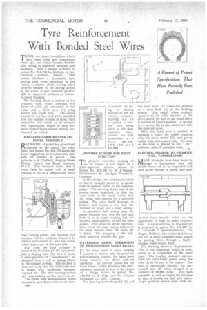
The drawing shows a section of the proposed tyre, which contains two layers of cable (2) embedded in the walls, and a third layer (1) lying around the whole tyre. The cables consist of very fine steel wires, moulded first into bonded strands of three, then remoulded into cables of 12 strands; this construction results in each filament of steel being almost entirely surrounded by rubber.
PARAFFIN CARBURETTER ON NOVEL PRINCIPLE
RATIONING of petrol has given fresh impetus to the search for other fuels, and patent No. 515,772 shows the latest suggestions for Is carburetter suit , able for paraffin or gas-oil. The patentee is A. Gladwell, Ampton. Street Works, Gray's Inn Road, London, W.C.1. This inventor states that if these fuels be mixed with a small amount of air at a temperature above
heir boiling points, the resulting rich mixture will not condense if later it be diluted with cooler air, and the carburetter makes use of this principle.
Fuel from the float chamberis metered by the main jet (2) and passes into a sloping tube (3); here it meets a small quantity of" superheated" air obtained from a coil of piping placed in the exhaust system. The mixture is then drawn. up into the choke tube and is mixed with additional exhaustwarmed air. The slow-running system (1) runs entirely on the extra-hot air.
The choke tube automatically varies its area in accordance with the air flow, P.30 loose balls (4) rising in sloping grooves as the air velocity increases. Starting up is on petrol, a twofuel cock being fitted to the float chamber. Other patents on this carburetter a r e N o s. 451,726, 450,495 and 457,669.
ANOTHER SCHEME FOR PILOT INJECTION'
T°promote smoother running of an oil engine is the object of a pilot injection scheme shown in patent No. 515,231 by R. L'Orange, Heidestrasse 48, Stuttgart-Feuerbach, Germany,
In this design, the preliminary spurt of fuel is brought about by a special type of delivery valve in the injection pump. The drawing shows one of the several forms described; in this, the valve seats on the usual conical face (2) being held thereon by a powerful spring. The valve itself, however, is hollow, and houses a free ball (1) between an upper and a lower seating.
In operation, fuel issuing from the pump chamber first lifts the ball and locks it in its upper seating, but not before a small quantity of fuel has been passed. This gives the initial injection, after which the main charge follows in the usual manner when the valve (2) is lifted. The dropping of the ball, after injection unloads the line.
EXTENDING SERVO OPERATION TO INDEPENDENT HAND BRAKE
IT has been usual in servo braking
systems to employ only the pedal for power-braking control, the hand lever being reserved for direct pull-rod operation. To provide power for the hand brake, whilst retaining the independence required by law, is the object of a design shown in patent No. 515,705 by S. Edge and the Clayton Dewandre Co., Ltd., Lincoln.
The drawing shows the pedal (2) and the hand lever (1) connected directly to a cross-shaft (4) of the braking system. The pedal, when worked, operates an air valve attached to the servo motor (3) and so the pedal effort Is assisted in known manner. A second servo motor (5) is also connected with the same air valve.
When the hand lever is worked, it operates a valve (6) which controls only the servo motor (6), and power comee from this source only. So soon as the lever is placed in the " off " position, valve 6 recimples both.
ELECTRIC CHARGE TO PROMOTE FUEL VAPORIZATION
MLANY attempts have been made to design a carburetter that will enable heavy oil to be vaporized and used in the manner of petrol, and such
devices have usually relied on the application of heat to assist evaporation. A novel addition to this method is proposed in patent No. 515,587 by C. Eickhoff, 7 Speenkruidstraat, The Hague, Holland, who claims that heavy oils can be finely atomized when heated by passing them -through a highlycharged electrostatic field.
The drawing shows a diagrammatic view of the apparatus, which is additional to a carburetter of the usual type. The roughly atomized mixture from the carburetter passes along the tube (1) on its way to the engine. The tube is electrically divided, the perforated part (2) being charged to a pressure of 65,000 volts. This high potential is said to ionize the mixture so that it breaks the fuel into microscopic particles which unite with air.