


A MULTI-SHOE BRAKE.
Page 32
If you've noticed an error in this article please click here to report it so we can fix it.
A Resume of Recently Published Patent Specifications.
FREDERICK H. ROYCE, Of Derby, describes in specification No. 226,032 a brake in which three or more shoes can act simultaneously in the drum, although one lining surface may wear faster than the others.
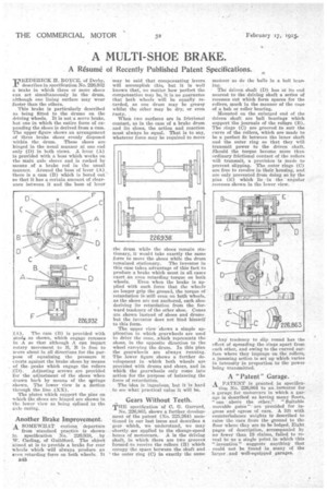
This brake is particularly. described as being fitted to the drums on the driving wheels. It is not a servo brake, but one in which the entire forte of ,expanding the shoes is derived from a cam. The upper figure shows an arrangement of three brake shoes evenly disposed within the drum. These shoes are hinged in the usual manner at one end only (D) in both views. A lever (A) is provided with a boss which works on the main axle sleeve and is rocked by insane . of a brake rod in the usual mariner. Around the boss of lever (A) there is a cam (B) which is bored out so that it has a certain amount of clearance between it and the boss of lever ; A). The cam (B) is provided with stud: as Shown, which engage recesses 'n A so that although A can impart rotary movement to B, B is free to move about in all directions for the purpose of equalizing the pressure it exerts against the brake shoes by means of the peaks which engage the rollers
i(D). Adjusting screws are provided for the adjustment of the shoes 'when drawn back by means of the springs shown. The lower view is a section through the line .(XX), The plates which support the pins on which the shoes are hinged are shown in the lower view as being Splined to the axle casing.
Another Brake Improvement.
.A SOMEWHAT curic;us, departure from -standard practice is shownin specification No. 226;038, , by W. Carling, of Guildford. The object 'aimed at is to provide a brake for rear svheels which will always produce an even retarding force on both wheels. It Z48 may be said that compensating levers will accomplish this, but it is well known that, no matter how perfect the compensation may be, it is no guarantee that both wheels will be equally retarded, as one drum may be greasy whilst the Other may be dry; or even rusty.
When two surfaces are in frictional contact, as in the ease of a brake drum and its shoes, the action and reaction must always be equal. That is to say, whatever force may be required to move the drum while the shoes remain stationary, it would take exactly-the same force to move the shoes while the drum remained stationary. The inventor in this case takes advantage of this fact to prodirce a brake which must in all cases exert an even retarding torque on both wheels. Even when the brake is applied with such force that the wheels no longer grip the ground, the torque of retardation is still even on both wheels. as the shoes are not anchored, each shoe deriving its retardation from the forward tendency of the other shoe. Cones are shown instead of shoes and drums. but the inventor does not bind himSelf to this form.
The upper view -shows a simple application in which gearwheels are used to drive the cone, _which represents the shoes, in the opposite direction to the wheel carrying the drum. In this plan the gearwheels are always running. The .lower figure shows a further development in which both wheels are provided with drums and shoes, and in whieh the gearwheels only come into action for the purpose of balancing the -force of retardation.
The idea is ingenious, hut it is hard to see what practical value it will be.
• Gears Without Teeth.
THE specification of C. G. Garrard, No. 226,863, shows a further development of the patent (No. 225,264) men" tioned in our last issue and describes a gear which, we understand, we may -shortly see applied to the change-speed boxes of motorcars.. A is the driving .shaft, in which there are two grooves formiid to receive the rollers (B) which occupy the space between the shaft and the outer ring (C) in exactly the same
manner as du the balls in a hall bear ing; • . , .
The driven. shaft (D) has at its end nearest to the driving shaft a series of recesses cut which form spaces for the rollers, much in the manner of the cage of a bah" or roller bearing.
Mounted on the enlarged end of. the driven shaft are ball bearings which support the journals of the rollers (B). The rings (G) are grooved to snit the curve of the rollers, which are made to be a perfect fit between the inner shaft and the outer ring so that they will transmit power to the driven shaft. Should the torque become more than ordinary frictional contact of, the rollers will transmit, a provision is made to prevent slipping. The outer rings (C) are free to revolve in their housing, and are only prevented from doing so by the pins (E) which lie in the angular recesses shown in the lower view.
Any tendency to slip round has the effect of spreading the rings apart from each other, and owing to the curved surface where they impinge on the rollers, a jamming action is set up which varies in intensity in proportion to the power being transmitted.
A "Patent" Garage.
A PATENT is granted in specifica tion No. 226O64 to an iirventor for a garage for motorcars in which a garage is described as having many floors, " one • above the other." "Suitable movable gates " are provided for ingress and egress.of cars. A lift with counterbalance weights is described to raise • the -cars from the ground to the floor where they are to be lodged. Eight pages of description, accompanied by no fewer than 18 claims, failed to reveal to us a single point in which this invention" suggests anything that could not be found in many of the larger and well-equipped garages. •