SERVO SYSTEMS 0 t AKE APPLICATION.
Page 16

Page 17

Page 18

Page 19

If you've noticed an error in this article please click here to report it so we can fix it.
Ways in Which the Effort Required rating the Brakes Can Be Lessened.
ANYONE who has driven a heavy vehicle in traffic, medium size, are capable of extremely rapid deceleranot assisted by the fact that so many other vehicles tion, so that the commercial vehicle driver who is following them finds considerable difficulty in exertagree that the labour involved in continually applying the brakes is very considerable. Matters are now on the road, such as private cars of large and ing sufficient pressure on the brakes to avoid ram
whether it he a bus, lorry or char-a-banes, will ming the car in front.
The Effect of Increased Speed.
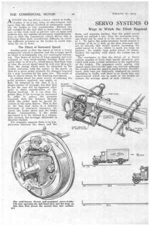
Another point is that the speed of which a heavy commercial vehicle is capable, and the average speed at which it is habitually run, are continually increasing. One hears of lorries of 3-ton capacity and over engaged on long cross-country haulage work averaging close on 20 m.p.h., which means that from time to time the actual speed must be well over 25 m.p.h. Now, the energy which must be absorbed by the brakes increases with the square of the speed, so that for a given pedal pressure the distance required for a stop increases by the same law. The result of this is clearly shown by the drawing reproduced. In casting about for some means of reducing the pedal pressure required, one might, at
first, be tempted to say that it is a 1W) 4E-L1E SP1.414.35,
simple matter of leverage, but that this is not the case will be apparent after quite a short consideration of the
factors involved. It is too often for1////
gotten that, if the leverage be increased in order to reduce the pressure required, then the distance through which the pedal must be moved increases in the same degree. This is due to the fact that there is a definite minimum of clearance necessary between the brake shoes and the brake drums. Consequently, if the pedal movement is to be limited to a reasonable amount, the leverage obtainable is likewise limited.
For example, suppose there is ant-in. clearance between the shoes and the
drum, and suppose, further, that the pedal travel should not exceed 4 ins., then the maximum leverage which can be used is in the same ratio, viz., 32 to 1. To halve the pedal pressure would require a leverage of 64 to 1, and, as the shoe clearance cannot be altered, this would involve increasing the pedal travel to 8 ins., which is much too large an amount. An unduly long pedal travel, of course, hapinpdlieerds. the rapidity with which the brakes can be The conclusion . is that the driver of a heavy vehicle capable of fairly high speeds should be provided with some outside assistance in the application of the brakes. The argument really applies with almost equal force to the light van, because although the weight is less the speed is much greater. Furthermore such vans are habitually employed on routes abounding in traffic, and there is no doubt that any improvement which can be made in the brakes increases the average speed of such vehicles.
There are several methods for augmenting the driver's effort in brake application, of which the most popular, so far, is the servo principle. This may be defined as "the use of a mechanism which employs the momentum of the vehicle to assist the driver in the application of the brakes." Broadly speaking, the mechanisms employed may be divided into two classes, viz., the self-contained servo-brake and the brake which is applied by an independent servo-motor.
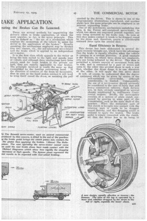
It is the first class which appeals to the writer as being the best suited to the light and speedy type of vehicle, and although these mechanisms have been mainly used for front brakes in the private car field, they are equally applicable to rear brakes. The principle involved is really the same as that exemplified by the familiar contracting band. If the direction of rotation of the drum be favourable, then so soon as the band makes contact it will tend to wrap itself round the drum, so assisting the pull exerted by the driver. This is shown in one of the diagrammatic illustrations reproduced, and another shows how the same principle can be employed in an internal expanding brake.
One of the best-known mechanisms embodying this idea is the Perrot self-contained servo-brake, in which two shoes are employed jointed together, one only being actuated by the brake cam. So soon as this shoe makes contact it tends to be dragged round by the drum and, therefore, exerts a considerable outward force upon the second shoe.
Equal Efficiency in Reverse.
This device has been elaborated in several designs recently brought out, which have the advantage that the brake is equally effective when the vehicle is running in a reverse direction. A good example is the Renaux, in which three shoes are employed, only one being actuated by the driver. This shoe is permitted a certain amount of movement from side to side, and is connected by a pair of levers and cams to the other two pivoted shoes in such a way that, whether the drum drags it in one direction or the other, it will apply the two servo shoes It will, of course, be understood that the degree of assistance which can be given by means of the self-contained servo-brake, although considerable, is limited. Consequently, the use of a servo-motor should seriously be considered in the ease of fairly fast and heavy commercial vehicles. Such devices are, in fact, already employed on several chassis constructed by well-known Continental makers. Briefly, the servo-motor consists of a species of plate clutch connected by gearing to some part of the transmission, such as the main shaft of the gearbox. When the stationary part of this clutch is brought into contact with the rotating part it tends to be dragged round thereby, and this dragging action is utilized to. apply the brakes. The brake pedal is simply connected with the clutch, all that the driver has to do being to bring the dutch plates into contact with one another. Rxperieuce in driving heavy private ears goes to show that such a system can be made extremely effective, quite a light pressure with the toe on the pedal _sufficing to apply the brakes to the full extent. Au important feature of any such servo-motor is the .way in which the clutch plates are a-etuated, it being necessary to arrange this so that, when the brakes come into action, further pressure on the i
clutch s avoided. If this provision were not made, one would lose sensitive control, with the result that the slightest pressure on the pedal would cause the servo-motor to take charge, as it were, and immediately apply the brakes to the full extent.
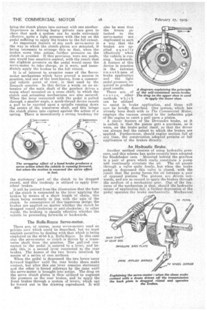
It is of interest to examine some of the Servomotor mechanisms which have proved a success in practice, and one of the best:known, from a commercial vehicle point of view,. is that used by the Renault concern. In this device a worm on an extension of the main shaft of the gearbox drives a worm wheel mounted on a cross shaft; to which the clutch and actuating mechanisms are also secured. When the lever connected with the pedal is pulled through a smaller angle, a quick-thread device causes a pull to be exerted upon a spindle running down the centre of the transverse shaft, and this brings the clutch plates into contact against the action of .a spring. There is immediately a strong tendency for
the stationary part of the clutch to be dragged round, and this tendency is utilized to 'apply fourwheel brakes.
It will be noticed from the illustration that the boss of the clutch is connected to the lever applying the brakes by means of a short length Of chain, this chain being normally in line with the axis of the clutch. In consequence of thisingenious 'design the brakes are applied no matter_ whether the clutch be dragged round clockwise or anticlockwise; in other words, the braking is equally effective whether the vehicle be proceeding forwards or backwar. ds.
The Rolls-Royce Servo-motor.
There are, of course, many servo-motors used on privlite 'cais which• could be described, but we must content ourselves by dealing with that which is being ern' PloYed on the 40-50 h.p:Rolls-Reyce. In this cue also the servo-motor or clutch is 'driven by a: transverse shaft from • the gearbox. The pull-rod eonnectedto the pedal is secured to a lever,' and beside this is a second lever connected to the rear brakes. The bosses of the two 'levers interlock by
means of a Series of cam 'surfaces. When the pedal is depressed the two levers carry forward together until the rear brake shoes make contact, but after this one lever remains stationary and the other: is forced sideways by the dams until the servo-motor is brought into action. The drag on the servo dutch plates is then' utilized to augment thepressure on the rear brakes, and to apply the front brakes through a system of levers which can be traced out in the drawing reproduced. It Will B34 also be seen that the levers attached to the servo-motor are duplicated in such a way that the brakes are applied equally effectively when the vehicle is running backwards. A. feature of this device in practice is the extreme smoothness of brake application and the light pedal pressure required to produce good results.
There are, of course, other methods which can be utilized
to assist in brake application, and these will now be briefly described. One system,which has already been dealt with in The Commercial Motor, employs the vacuum created' in the induction pipe of the engine to exert a pull upon a piston.
A clever 'feature of the Dewandre brake, as it is called, is that the piston gets a purchase, as it were, on the brake pedal itself, so that the driver can always feel the extent to which the brakes are applied. Furthermore, should engine suction fail at any time, the construction adopted permits of full application of the brakes directly.
An Hydraulic Brake.
Another method consists of using hydraulic-pres, sure, and this scheme has quite recently been adopted for Studebaker cars. Mounted behind the gearbox is a pair of gears which really constitute a pump and continually circulate the oil. The oil passes through a valve quite freely, but when the brake pedal is depressed this valve is closed, with the result that the pump forces the oil between' a pair of opposed pistons. The pistons are driven outwards, and are so caused to apply the brakes through the medium of a mechanical gear. One of the features of the mechanism is that, should the' hydraulic means of application fail, ,a ftirther depression of the . pedal 'operates the brake mechanically. Mechanical February 17, 1925. 19 • operatIon must, of course, also be relied upon for holding the vehicle against running backwards, because the pump is not reversible.
Although not strictly speaking a servo system, the subject would not be adequately treated without mention of the Westinghouse power brake,. which represents a very excellent method of reducing the labour involved to a minimum, and which has already achieved quote a degree of success, particularly for tractor-lorries. As recently recorded in The Cominercull Motor, the Westinghouse system can now be
• obtained with a pedal control, if desired, in place of the hand control previously fitted to the steering column. With the pedal control, the driver can feel the extent of brake application because, in operating the valve, the pedal reacts against a diaphragm subject to air pressure. One advantage of this system is that complicated mechanical gears are done away with, the pneumatic cylinders being placed as close to the brakes as desired. Furthermore, it is a .system which seems eminently suited to four-wheel-brake application, and there can be no question that four-wheel brakes will eventually become adopted by commercial vehicle manufacturers, not only owing to the increased rate of retardation which they confer, hut also because of the safety with which they can be applied on greasy roads.


