


CUTTING DOWN ROAD SHOCKS.
Page 10
Page 11
If you've noticed an error in this article please click here to report it so we can fix it.
A New Device which Carries a Solid-tyred Vehicle on an Air-filled " Buoyancer tnd Reduces Vehicle Vibration and Shock to Roads.
THE condition of the roads. and tracks in an area north of the city of Bombay has brought about the introduc, tion of a. new system of suspending heavy .vehicles on air which may have a far-reaching influence on vehicle comfort . in that country. The authorities and private enterprise in . Bombay are engaged, through the medium of the Bombay , Improvement Trust, in rehousing a large portion of the native population, clearing away slum areas and erecting . dwellings that offer some prospect of the .maintenance of
• desirable.studtary conditions. The Trust employs about 8,000 native workmen and labourers and has a number of• moter vehicles engaged in the transport of materials, stares and workers. The work is so arduous, mainly because of the rough ground to be traversed, that the springs of the vehicles are constantly being broken, and it behoved Mr. T. R. Sneyd K3mnereley, who is the executive engineer of the Trust, to endeavour to effect some alteration which should diminish or
put a stop to the trouble. He experimented with shock absorbers and with springs of various strengths, dimensions and character; he tried different devices of a more or less complicated order, and eventually reached an extremely simple method which has given full promise of overcoming his difficulties. The method has been developed and has now been patented in all essential -countries, while a syndicate has been formed in Great Britain to exploit it, Major T. G. Tuliach, of 28 and 29, Chettpside, London, EC, taking a leading part in its commercial development.
What Mr. Kynnersley has done has been to interpose between one end of each ordinary laminated spring and the
chassis frame an " lmoyancer," or bolster, bolted to a bracket, with a beam or lever arm which transfers the weight of the vehicle and its load to the buoyancer. Simple as the device sounds and actually is, there are a number of points of design, construction and employment where errors can occur, and, as is usual with any new device where "something similar" can be pointed to in the files of the Patent Office, failure of previous efforts to employ methods somewhat akin to those now under description has arisen through these errors being allowed to creep in.
For instance, it is desirable, whilst having the buoyancer firmly secured to one plate of the "nutcracker," that it should always tend to centre itself upon the other plate, The
ideal form of these two plates is perfectly flat, but a slight curve-tare is .permissible and gives the centring effect required, but it is important that the curvature should not exceed in the radius of the outer shell of the buoyancer under maximum flexure. A cover buttoned to the plates excludes dust and water.
The buoyaucer is made of canvas ,and rubber moulded and vulcanized, just as a tyre would be (the makers of those we have inspected and tested are David Moseley and Sons, Ltd., of Manchester, who have taken a great interest in the production of a bolster entirely suited to the work). It is made in various sizes from about a foot long by 3i ins. in diameter for Fords (four being employed, all of the same size) to 28 ins. long by 6 ins, in diameter for the rear axles of lorries, buses and motor coaches, the size of the buoyancer for the • front axles of those vehicles being 16 ins, long by 6 ins. diameter. ,
Formed along the upper edge is a rib, embedded in which are the heads of the security studs. A bed is formed in the face of the tipper plate bracketed to the frame of the vehicle to take this rib, and the buoyancer is bolted thereto by thumbscrews screwed on to the studs. A valve for inflation purposes passes through the rib and protrudes above the holding plate. The lining is vulcanized in the buoyancer, and is not a separate inner tube, as there is no need for that 'form of construction.
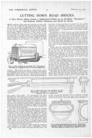
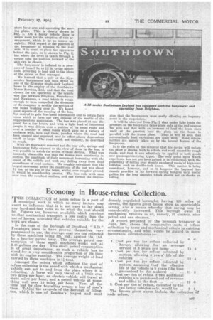
The lower plate, slightly concave, in transverse section, is secured to a beam pivotally mounted on a bracket bolted to the frame of the vehicle about 16 ins. or 18 ins, from a point in line with the spring centre. The end of the spring is shackled, not to the vehicle frame, but to the beam, close to the end of the buoyancer plate. The end of the beam can move, in a guide, if it be thought necessary, and rubber stops are incorporated so that any banking effect under severe shock is taken by the stops and not by the buoyancer. The design thus described and illustrated in Fig. 2 is suitable for front axles and rear axles, but there are alternatives. Where there are stays, dynamo mountings and such like.' which would interfere at the rear of a front spring, the bracket carrying the buoyancer may be mounted vertically outside of the frame and in the angle formed by the dashboard and bonnet,' the end of the spring being attached to a
short lever arm and operating the moving plate. This is clearly shown in Fig. 1. On a heavy vehicle there is ample room for the adoption of this arrangement, which is by no means unsightly. With regard to the position of the buoyaneer in relation to the rear axle, it is usual to place the apparatus behind the axle, as is shown in Fig. 2, but where the drive is taken through a torque tube the position forward of the axle can be chosen.
The buoyancer is inflated to a pressure of from 8 lb. to 12 lb. to the square inch, according to load and to the ideas of the driver or fleet manager.
We learned that a pair of the Kynnersley buoyaneers had been fitted on ume of the 32-seater single-deck Leyland buses in the employ of the Southdown Motor Services, Ltd., and that the road chosen for the operation of the vehicle was that between Brighton, Peacehaven and Newhaven, a road which is rough enough to have compelled the directors of the company to modify the springs of the buses working over it. We heard good reports of the running of the bus, hut desired to gain first-hand information and to obtain facts upon which to form our own opinion of the merits of the supplementary suspension. The bus was placed at our disPosal for a few hours, and with a light load of interested people it was driven over a portion of its usual route and over a number of other roads which gave us a variety of surfaces with, here and there, patches where the road bad
• been opened and repaired, and in other -places depressions small or large. The road could, not unfairly, be described as rough.
With ths floorboard removed and the rear axle, springs and biloyancers fully exposed to the view of those in the bus, it was possible to watch the action of those devices. What was instantly observable was that the beams were constantly in motion, the amplitude of their movement increasing with the speed of the vehicle and with any falling away from dead smoothness of road surface. We roughly calculated that the largest movement under the conditions of the test was about 11 ins, at the /1p of the beam, whilst over rougher ground it would be considerably greater. The bus rode with ease over even the roughest surface, and one formed the impres
slop that the buoyancers were really effecting an improvement in the suspension. It will be observed from Fig. 2 that under light loads the Pressure on the buoyancer takes place only at the end nearest the axle and that with an increase of load the beam rises until at the greatest load the plate on the beam is parallel with the frame plate. Thus it will be seen that automatically load variations are dealt with. Road irregularities are mainly taken up by the lateral flexure of the buoyancer.
It is the claim of the inventor that his device will reduce the effect of shocks, both to vehicle and road, caused by rough roads, and that it can 'effectively be applied to both goods and passenger-carrying types. The only point upon which experience has not yet been gained is in connection with the possibility of rolling over steeply cambered roads 'of high-load vehicles, such as double-deck buses. This matter is being considered, however, and as it happens the Leyland bus chassis provides in its forward spring hangers very useful guides for the long shackles which should act as checks on rolling.