


AUTOMATIC CHANGE-SPEED GEARS..
Page 28
If you've noticed an error in this article please click here to report it so we can fix it.
A Résumé of Recently Published Patents.
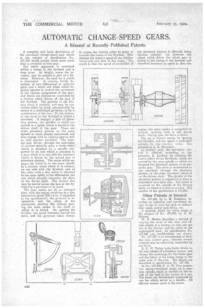
A complete and lucid description of the automatic change-speed gear which is the subject of specification No. 127,122 would occupy much more room than is available on this page. The whole apparatus is contained within a recess in,the flywheel and a deep cover. Its Weight, states the inventor, may be utilized in part assa flywheel. Moreover, the need for a clutch
is eliminated. It consists, briefly described, of two differential or epicyclic gears and a Worm and wheel which together operate to control the movement of the various components of the gear, and which are themselves controlled_by a friction wheel driven off the face of the flywheel. The position of the friction wheel is variable, and may be CCIAtrolled either by hand, automatically by means of a centrifugal goVernor;.or'hy "a combination of the two. •To theinterior of the cover to the flywheel' is batted a sunwheel. It engages a pair of planetary pinions, the spindles of whieh are carried in a spider.which is keyed to the driven Shaft of the gear. There are other planetary pinions on the 'same' spindle as those already mentioned; and they engage with an internal gear as. well as with another sunwheel. The internal gear drives, through the equivalent of another epicyclic gear, a worm wheel. which is mounted on a spindle supported by an arm which is attached to a boss which is in one with the sunwheel which is driven by the second pair of planetary pinions. The worm which engages the wheel is on the same spindle as a friction wheel which is in contact, on one side with the flywheel, and on the other. with a disc which is attached to the main spider of the differential, the one which actually transmits the drive to the driven shaft. The friction disc may be moved across the face of the flywheel by a governor or by hand..
The gear ratios are all so arranged that, with the engine revolving at a predetermined speed (200 r.p.m. is suggested in the specification), the governor is inoperative, and the whole of the mechanism revolves idly without moving the main spider or the shaft to which it is keyed. On opening the throttle, the speed increases beyond the limit, and the governor takes charge, It. causes the friction. roller to move in towards the centre of the flywheel. This reduces the relative speed of the friction wheel and also that of the worm. The result is that the speed of revolution-of the planetary pinions is affected, being likewise reduced. As, however, the wheel which drives the whole gear is bolted to the casing of the flywheel and therefore increases in speed as does the engine, the, main spider is compelled to revolve, carrying with it the driven shaft: top gear the drive is direct.
The car is started merely by opening the throttle, and the speed is controlled Aritirely by the.' thxottle valve. The patentee' is A. R. Bannister.
In another gear, the automatic con' treil— is effeeted, according to the patentee, R. Lindsay, by utilizing the inertia effect of two flywheels, which are carried by the same spindle to which are fastened the planetary pinions of an epicyclic gear. The drive is transmitted to one sunwheel, through the planetary pinions' to the other sunwheel, which is on the driven shaft. The spindle of the planetary pinions is supported in what is referred to as a train arm. The latter is mounted on the outside of the driving shaft, on which it is free to revolve. The number of the specification is 137,205.
Other Patents of Interesf.
No. 137,124, by L. M. Hadgkiss, describes an ingenious and convenient design of cap or cover for such as radiator filler pipes, petrol tank fillers, etc. A packing gland for valve stems is the subject of No. 137,088, by G. H. Skinner.
W. E. Martin describes a method of varying the level of the near and offside wheels of a tractor, so that one can run in the furrow, and the other on the unploughed land. In specification No. 137,106 two modifications are shown.
No. 137,107 is an arrangement of Bowden wire control gear, whereby several controls may be selectively controlled by one lever.
L. F. W. Tetley bolts brake' driin ia to the rear wheels of a Fordson tractor, and clamps the anchorage for the brake gear and the fulcra of the brake straps to the outer case of the axle. The details are described in specification No. 137,126. . In No. 137,169, F. 0. W. New mounts two spring-restrained hooks on a corn, mon spindle which ,is .carried on the inside of the. Wall Of 'the borMet of a ear. The hooks are furthermore connected by one bar which serves as a handle. An efficient bonnet catch is the result.