


The Bendix Contribution to Road Safety and Efficiency
Page 9
Page 10
If you've noticed an error in this article please click here to report it so we can fix it.
Latest Developments in Cowdrey Heavy duty Brakes, in Braking-force Distribution, Devices and in Testing Apparatus
So firmly is the name Bendix connected with the servo or selfenergizing shoe, that few people realize the wide range of brakes which are manufactured by Bendix, Ltd., at its factory in King's Road, Tyseley, Birmingham. The Cowdrey range of heavy-duty brakes is available either with self-energizing shoes Or in nonservo form, and with hydraulic, pneumatic or mechanical operation.
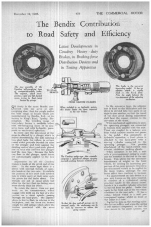
In every case the movement of the two steel halls (or rollers, in certain cases) which protrude beyond the sides of the 'plunger and bear against the slanting ends of short push-rods, placed one on each side between the plunger 'and the shoe tips. Because the balls can float in the plunger, equal forces are automatically applied to the two shoes.
Adjustment on all the Cowdrey brakes is made at the pivot end of the shoe. In the servo type there is a sleeve with internal threads of opposite hands at the two ends. It controls the position of two short rods screwed into it which carry at their outer ends tile pivots for the brake shoes. The threads are not of equal pitch but allow for the fact that one facing wears more slowly than the other.
To rotate the sleeve, there are gear teeth on its circumference, which engage with teeth on the face of a disc carried on a short spindle passing through the back-plate. The adjuster sleeve•is free to float, in relation to the back-plate, and the shoes are located simply by stiff springs which allow the niotion associated with the servo action. In the non-servo type, the adjuster unit is fixed to the back-plate and the sleeve is divided into two parts at an angle to one another, so that the travel of the shoe pivot during adjustment . shall bear the correct relation to the curvature of the drum.
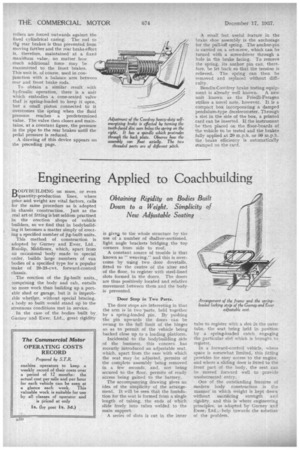
When mechanical application is used, the operating plungers are connected to tension rods parallel with the. axle. These are coupled to a balance arm from which another tension rod passes to the pedal. For pneumatic or A hydraulic operation, a fixed piston is attached to the back-plate with a moving cylinder connected to the operating plunger. This permits attachment of the hand-control rods without additional packing glands. When operation is by rod, a unit with a pre-compressed Spring is available for inSertiOn in the rod to the rear brakes. This allows for the inevitable transference of weight to the front Wheels, by causing' an increasing proportion of the pedal pressure (beyond a pre-determined value) to be applied to the front brakes, although the rear brake effect does continue to increase. An improvement on this device is a new unit known as the Auto Control. It consists of a cylindrical .casing attached rigidly to the chassis frame. Inside it is a smaller cylinder attached to the rod from the pedal. Inside that again is the front end of the rod which continues to the rear axle. It has a collar, behind which is a stiff precompressed ,spring, whilst in front of the collar is a cone.
CAried in slots in the moving cylinder are two rollers, and when the spring is still further compressed, so that the cone moves in the small cylinder, the
rollers are forced outwards against the fixed cylindrical casing. The rod to th rear brakes is thus prevented from moving farther and the rear brake effort is, therefore, maintained at a fixed
maxirhum value, no matter how much additional force may be transmitted to the front brakes. This unit is, of course, used in conjunction with a balance arm between rear and front brake rods.
To obtain a similar result with hydraulic operation, there is a Ludt which embodies a cone-seated valve that is spring-loaded to keep it open, but a small piston connected to it overcomes the spring when the fluid pressure reaches a predetermined value. The valve then closes and maintains, at a constant figure, the pressure in the pipe to the rear brakes until the pedal pressure is reduced.
A drawing of this device appears on the preceding page. A small but useful feature in the brake shoe assembly is the anchorage for the puIloff spring. The anchor-pin is carried on a set-screw, which can be turned with a screwdriver through a hole in the brake facing. To remove the spring, its anchor pin can, therefore, be let back so that the tension is relieved. The spring can then be removed and replaced without difficulty.
Bendix-Cowdrey brake testing equipment is already well known. A new unit known as the Friedli-Feragen strikes a novel note, however. It is a compact box incorporating a damped pendulum-type decelerometer. Through a slot in the side of the box, a printed card can be inserted, If the instrument be then placed on the floor-boards of the vehicle to be tested and the brakes fully applied at 20 m.p.h. or 80 m.p.h. the brake efficiency is automatically stamped on the card.