


Optional Two-wheel or Four-wheel Drive
Page 28
If you've noticed an error in this article please click here to report it so we can fix it.
A Resume of Recently Published Patent Specifications That Are Obtainable From the Patent Office, Price i s. Each
E1ROM Dahnler-Benz A.G., Stuttgart
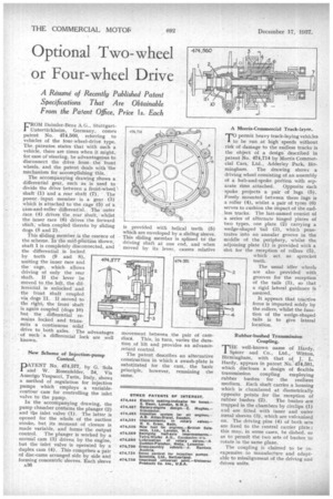
Unterttirkheim, Germany, comes patent No. 474,560, referring to vehicles of the four-wheel-drive type. The patentee states that with such a vehicle, there are times when it might, for ease of steering, be advantageous to disconnect the drive fromthe front wheels, and the patent deals with the mechanism for accomplishing this.
The accompanying drawing shows a differential gear, such as is used to divide the drive between a front-wheel , shaft (1) and a rear shaft (7). • The powerinput member is a gear (3) which is attached to the cage (5) of a 'cam-and-roller differential. -The outer race (4) drives the rear shaft, whilst the inner race (6) drives the forward shaft, when coupled thereto by sliding dogs (8 and 2).
This sliding member is the essence of the scheme. In the mid-ptisition Shown, shaft 1 is completely disconnected, and the differential is locked by teeth (9 and 8), uniting the inner race and the cage, which allows driving of only the rear shaft. If the lever be moved to the left, the differential is unlocked and -the front shaft coupled via dogs 11. If moved to the right, the front shaft is again coupled (dogs 10) but the differential remains locked and transmits a continuous solid' drive to both axles. The advantages of such a differential lock are well
• known.
New Scheme of Injection-pump Control.
DATENT No. 474,577, by G. Sola 1 and W. Rosenfelder, 54, Via Arnerigo Vespucci, Turin, Italy, shows a method of regulation for injection pumps which employs a variablecontour cam for controlling the inlet valve to the pump.
In the accompanying drawing, the pump chamber contains the plunger (2) and the inlet valve (1) . The latter is opened for the whole of the suction stroke, but its moment of closure is made variable, and forms the output control. The plunger is worked by a normal cam (3) driven by the engine, but the inlet valve is operated by a duplex cam (4). This comprises a pair of disc-cams arranged side by side and forming concentric sleeves. Each sleeve
A36 A Morris-Commercial Track-layer.
7'0 permit heavy track-laying vehicles to be run at high' speeds without risk of damage to the endless tracks is the object of a design described in patent No. 474,714 by Morris Commercial Cars, Ltd., Adderley Park, Birmingham The drawing shows a driving wheel consisting of an assembly of a hub-and-spoke portion with sep
arate rims attached. Opposite each spoke projects a pair of lugs (5). Freely mounted between these lugs is a roller (4), whilst a pair of tyres (6) serves to cushion the impact of the endless tracks. The last-named consist of a series of alternate hinged plates of two types, one plate (2) carrying a wedge-shaped tail (3), which penetrates into an annular groove in the middle of the periphery, whilst the adjoining plate (1) is provided with a slot for the reception of rollers (5), which act as sprocket teeth.
The usual idler wheels are also provided with grooves for the reception of the tails (3), so that a rigid lateral guidance is assured.
It appears that tractive force is imparted solely by the rollers, whilst the Junction of the wedge-shaped tails is to give lateral location.
Rubber-bushed Transmission Coupling.
THE well-known name of Hardy, Spicer and Co., Ltd., Witton, Birmingham, with that of J. L. Hardy, appears in patent No. 474,581, which discloses a design of flexible transmission coupling employing rubber bushes for the resilient medium. Each shaft carries a housing which is chambered at diametrically opposite points for the reception of
rubber bushes (2). The bushes are trapped in the chambers by circlips (1) and are fitted with inner and outer metal sleeves (3), which are vulcanized on. The driving pins (4) of both sets are fixed to the central carrier plate : this may, in some cases, be dished, so as to permit the two sets of bushes to rotate in the same plane.
The coupling is claimed to be inexpensive to manufacture and adaptable to misalignment of the driving and driven units.