


Patents Completed.
Page 22
If you've noticed an error in this article please click here to report it so we can fix it.
Complete specifications of the following patents will be sent to any address in the United Kingdom upon receipt of eightpence per copy at Sales Branch, Patent Office, Holborn, W.C.
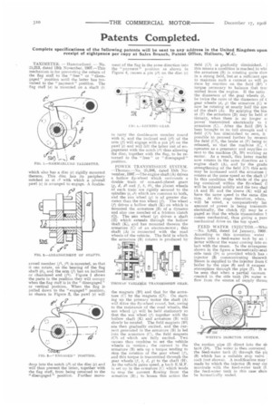
TAXIMETER. — Hammarlund. — No. 25,213, dated 13th November, 1907.—This mechanism is for preventing the return of the flag staff to the "free" or " disengaged " position until the latter has traversed to the " payment " position. The flag staff (a) is mounted on a shaft (b) which also has a disc (c) rigidly mounted thereon. This disc has its periphery notched as at 62 with which a pivoted pawl (e) is arranged to engage. A double armed member (fl, tl) is mounted, so that it can rotate, on the bearing of the flag shaft (b), and the arm (f) has an inclined or chamfered end (f1). Figure 1 shows the parts in the position they will occupy when the flag staff is in the " disengaged " or vertical position. When the flag is pulled down to the " engaged " position, as shown in Figure 3, the pawl (e) will drop into the notch (c2) of the disc (e) and will thus prevent the latter, together with the flag staff, from being returned to the "disengaged" position. Further move ment of the flag in the same direction into the " payment " position as shown in Figure 4, causes a pin (c3) on the disc (e) to carry the double-arm member round with it, and the inclined end (f1) of the arm (f) will engage with a pin (el) on the pawl (e) and will lift the latter out of engagement with the notch (c2) thus allowing the disc, together with the flag, to be returned to the "free" or " disengaged " position.
POWER TRANSMISSION SYSTEM. —Thomas.—No. 25,386, dated 15th Novembee, 1907.—The engine shaft (A) drives a hollow fly-wheel which surrounds a double train of sun-and-planet gears (g, d, dl and f, b, bl), the planet wheels of each train are rigidly secured to the spindles (e, Cl) which are common to both, and the sun wheel (g) is of greater diameter than the .sun wheel (f). The wheel (f) drives a hollow shaft (K) on which is mounted the armature (13) of a dynamo and also one member of a friction clutch (Q). The atm wheel (g) drives a shaft (II) which extends through the hollow shaft (K), and has mounted thereon the armature (C) of art electro-motor ; this shaft (A) is connected with the road wheels of the vehicle. The field in which the armature (B) rotates is produced by the magnets (B1) and that for the armature (C) by the magnets (Cl). On starting up the primary motor the shaft (A) will drive the fly-wheel round, but, owing to the resistance of the road wheels, the sun wheel (g) will he held stationary so that the sun wheel (f) together with the hollow shaft (K) and armature (B) will slowly be rotated. The field magnets (Bi) are then gradually excited, and the current generated in the armature (B) is led into the armature (C), the field magnets (Cl) of which are fully excited. Two causes then combine to set the vehicle wheels in motion ; the current in the armature (13) sets up a torque tending to stop the rotation of the gear wheel (f), and this torque is transmitted through the gear wheels (f, b, if, g) to the shaft (H). As the vehicle gains speed, a back E.M.F. is set up in the armature (C) which tends to stop the current flowing from the armature (B) ; to lessen this action the field (C1) is gradually diminished. this means a condition is reached in whi the armature (B) is rotating quite slow in a strong field, hut at a sufficient ape to maintain such a current as will pa duce by reaction on the field (B1) t torque necessary to balance that trar mitted from the engine. If the ratio the diameters of the gear wheels (b, be twice the ratio of the diameters of t gear wheels (d, g) the armature (C) w now be rotating at nearly half the spa of the shaft (A). By applying the bra at (P) the armature (B) may be held at tionary, when there is no longer at power transmitted electrically to t: armature (C). After the field (B1) h been brought to its full strength and tI field (C1) has diminished to zero, it possible to proceed further by reversit the field (C1), the brake at (P1 being nc released, so that the machine (C, C operates as a generator and supplies cu rent to the machine (B, B1) working as motor. As a result, this latter machil now rotates in the same direction as t! engine shaft (A), and by the gradu strengthening of the field (CI) this antic may be increased until the armature (. rotates at the same speed as the shaft (fi In this condition the whole of the gee ing contained within the fly-wheel (1 will be rotated solidly and the two shaf (A and H) and the sleeve (K) will al have the same speed in the same dire tion. At this stage therefore, when, will be noted, a comparatively lar amount of power is being transmit, electrically, the clutch (QI may be e gaged so that the whole transmission 1comes mechanical, thus giving a pure mechanical drive on the top speed.
FEED WATER INJECTOR.—Whit —No. 5,022, dated 1st January, 1908.. According to this invention water drawn into a feed-water tank by an i jector without the water coming into co tact with the steam. In the arrangeme shown in the figure a hermetically-seal, side tank (1s) is provided which has t injector (3) communicating therewit Steam is supplied to the injector from ti boiler by the pipe (6) and it escapes atmosphere through the pipe (7). It w be seen that when a partial vacuum created in the side tank (18.) water w flow from the source of supply throlq
the suction pipe (2) direct into the sit tank (1s). The water is then conveyed the feed-water tank (1) through the pi) (8) which has a suitable stop valve , cock (not shown). A modification may I made by which the injector (3) may cot municate with the feed-water tank (1: the feed-water tank in this case shou be hermetically sealed.