


Self-servo Brake Mechanism
Page 68
If you've noticed an error in this article please click here to report it so we can fix it.
BRAKE mechanism that provides its own hydraulic amplification is shown in patent No. 89,1.951. 'Though intended mainly for disc brakes, the patent covers also the principle applied to drum brakes. (National Research Development Corporation. 1 Tilney Street, London. W.I.)
The drawing clearly illustrates. the principle of the device. The brake disc or drum (1) is fitted with a contractible band-brake (2) operated manitally, by a cable (3) or other convenient means. This forms the trigger of the system; when the band-brake is applied it naturally attempts to rotate .with the disc.
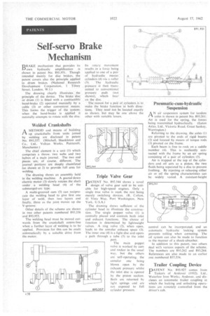
Welded Crankshafts
PAA METHOD and means of" building up crankshafts from units joined by welding are disclosed in patent No. 893.357. (Mitchell, Shackleton and Co.. Ltd.. Vulcan Works, Patricroft, Manchester.)
The chief element is a unit (I) which comprises a throw. two webs and two halves of a main journal. The two end pieces are. of course, different. The journal portions are deeply chamfered (as shown at 2) to provide full area for welding.
The drawing shows an assembly held in the welding machine. A geared-down electric motor (3) slowly rotates the shaft under a welding head (4) of the submerged-arc type.
A multi-grooved cam (5) can reciprocate the welding head to give first one layer of weld, then two layers and finally, three as the joint moves up the V-groove.
Other details of the scheme are shown in two other patents numbered 893.356 and 893,955.
The welding head must be moved outwards from the crankshaft centre-line when a further layer of welding is to be applied. Provision for this can be made automatically by a suitable drive from the motor_
Its rotary, movement results in a force being applied to one of a pair of hydraulic master. cylinders (4) via a roller (5). The hydraulic pressure i then transmitted to conventional
pressure pads (not . shown), which bear on the Oise..
The reason for a pair of cylinders is to make the brake function in both direc
tions. They need not be located exactly as shown, but may be one above. the other with suitable levers.
Triple Valve Gear
DATENT No. 892.544 shows a novel
design of valve gear said to be suitable for high-speed engines. Only a single true valve is used, the rest being merely switching devices. (R. Colton. 41 Vista Way. Port Washington. New York. U.S.A.) The drawing shows sufficient of the cylinder head to illustrate the construction. The single poppet valve (1) is centrally placed and controls both inlet and exhaust functions. The choice of function is determined by lightweight valves. A ring valve (2), when open. leads to the annular exhaust space (3). The inner one (4) is a light disc and opens a path through a tube (5) to the inlet port.
The main poppet valve is worked by earn and rocker in the usual way, but the others are self-operating, the annular one being blown open by the exhaust pressure whilst the inlet disc is opened by the piston suction. Both are returned by light springs and are not exposed to full cylinder pressure.
Pneumatic-cum-hydraulic Suspension •
A N air suspension system for tandem axles is shown in patent No. 893,26I' Air is used for the spring, the forces being transmitted hydraulically. (Eaton. Axles. Ltd.. Victoria Road. Great Sankey. Warrington.)
Referring to the drawing, the axles (.1) are pivoted to the ends of rigid beams (2) and located by means of torque rods (3) pivoted on the frame. • Each beam is free to rock on a saddle member (4). This is resiliently connected with the frame by an air spring consisting of a pair of cylinders (5).
Air is trapped at the top of the cylinders. and_ oil acts as a piston, the two fluids being separated by a disc to prevent frothing. By injecting or releasing either air or oil the spring characteristics can be widely varied. A constant-heigh control can be incorporated, and an automatic hydraulic locking system prevents rolling when cornering. The oil system can also be made to function in the manner of a shock-absorber.
In addition to this patent, two others deal with various aspects of the scheme, The numbers are 893.262 and 893,264. References are also made to an earlier one numbered 857.554.
Trailer Coupling Device
DATENT No. 893.927 comes from
Taskcrs of Andover (1932). Ltd., Waterloo Iron Works. Andover, and discloses an automatic trailer coupling in which the locking and unlocking operations are remotely controlled from the driver's cab.