


A Friction-driven Infinitely Variable Gear
Page 58
If you've noticed an error in this article please click here to report it so we can fix it.
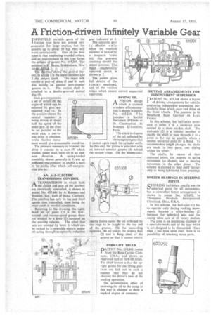
INFINITELY variable gears of the I friction type have not proved very , 4uccessfu1 for large engines, but for • powers up to about 10 11.p. they will ' work:satisfactorily. One of .the best types is that employing toroidal rollers, and an improvement in this type forms the subject 44 patent•No. 655,307. The pate-pteeis..F. Hayes, Middletown, New ier -$44
e wineshows` the general lay outtn 1 is the input member and 2 the output shaft. The -input side
carriesa• pair of discs (3 and 4) each disc having an annular part-circular
groove in it. The output shaft is attached to a double-grooved central disc (5).
• Each gromv.ontains a set of rollers (6). the, angle of Which can he adjusted to give .-any required rati o.• In • the position shown the central • member ' isbeing driven at about half the speed of the outer pair. If the discs he set parallel to the main axis, a one-toone drive is obtained, whilst further move
ment would give a reasonable overdrive. The pressure necessary to transmit the drive if created by a cam (7) which
• pushes, under load, balls (8) in an endwise direction. A spring-loaded assembly, shown generally at 9, sets up :sufficient ,end-pressure to enable astart to be made, after which self-energization Sets in.
AN ALL-ELECTRIC
• TRANSMISSION CONTROL
ATRANSMISSION in . %/vhieh both the clutch and part of the gearbox are electrically controlled, is shown in patent No. 655,441 by A. Kamper and
• Humber, Ltd. both of Stoke. Coventry. The gearbox has only its top and third • speeds thus :controlled, these being the , most used in normal. conditions.
-. Referring to the drawing, the righthand set of gears (1) is the first-, ' secondand reverse-speed group; these • are worked by a lever (2) mounted on the steering column. The other two sets are selected by lever 3, which can be rocked by a reversible electric motor (4) acting through an epicyclic reduction • gear indicated at 5.
The epicyclic gear is effective on 1y when its reaction member is locked by a magnetic brake (6); this prevents straining should the motor overrun.: The. main ....magnetically operated clutch is
shown at 7. • The patent gives full details of the circuit employed, and Of the various relays which ensure correct sequential Operation.
• SAVING OIL
APISTON design which is claimed to reduce oil cansurrip-' ti on. is ShOW11. in patent .No. . 655,324. T h e • patentee is • Societe.Nationale D'Etude et de Construction . de Moteurs D'Aviation, Paris.
The aim is to dispose of the oil collected by the scraper rings so that it cannot again reach the cylinder walls. To this end, the piston is provided with an internal annular groove 41.) behind, the scraper rings. On the downstroke, inertia forces cause the oil collected by the rings to Ixf. canght.in the top end of the groove. • On the Succeeding --upstroke, the oil strikes the sloping face (2) and is flung clear of the 7 groove so that it cannot retarh.
FORK-LIFT TRUCK
PATENT 1Vo. 654,866,cornes from the Ross Carrier Cam-. pany, U.S.A., and shows., an improved type of fort-lift thick. • The chief feature is that the Upright guides for the lifting platform are laid out in such a manner that they do not obstruct the driver's view of the loading operation.
The accumulative effect of returning the oil to the sump in this way is claimed to show a marked degree of economy. DRIVING ARRANGEMENTS FOR INDEPENDENT SUSPENSION
PATENT No. 655,168 shows a layout of driving arrangements for vehicles employing independent suspension, particularly those Which steer-and drive on the front wheels. The patentee is G. Bnirchard, Saint German' • en Laye, France.
In this scheme, the half-axles terminate at point I in .a universal joint carried by a short cardan .shaft. The stub=axle (2) is a tabular' member to enable the shaft to pass through it to a point as far out as possible where a second universaljoint (3) is fitted. To accommodate length changes, the shafts are made in two parts, one sliding Within the other, The shafts, by reason of their Universal joints, can respond to spring. movement (as shown), and to steering movement.in the other plane. The scheme is claimed to lend-itself favaurably to being fabricated from pressings.
ROLLER BEARINGS IN STEERING JOINTS
S'ERING ball-jeints usually use the spherical parts for all movements, but a somewhat better arrangement is shown in patent No 655,092,— by Thompson Products Incorporated.
Cleveland,. Ohio, U.S.A. .
In this scheme, the ball-joint: (1). has to operate only during rocking movements, because a .roller-bearing' (2) between • the •spherical seat and the . casing takes care-of -all rotary Motion. The joint is an interesting example of a specialist-made unit of the type which is not designed to be dismantled. Once edge 3 has been spun over, there is no possibility of renewing worn parts.