


A Design for an Automatic Gearbox
Page 36
If you've noticed an error in this article please click here to report it so we can fix it.
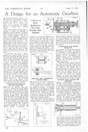
A Resume of Patent Specifications That Have Recently Been Published
A SEMI-AUTOMATIC gearbox, tiav ing several novel features, is shown in patent No. 569,410, by O. Wolff, Chestnut Hill, Mass., U.S.A. The device relies for its •self-changing action on the difference in friction between a slipping and a driving 'clutch.
The drawing shows a simple form of gearbox in which the principle is applied to only two speeds. The engine shaft ( I ) carries with it a casing (2) and a tubular gearshaft (3), all of which revolve together. Inside the casing is an oil-filled centrifugal clutch, the driven member of which is connected to the central shaft (4). The output shaft of the gearbox can he dog-clutched to gear 5 and the latter can be driven by one of two routes— direct when the clutch is driving, or via the gear-train (6) when it slips, when a reduced ratio is obtained. The other gears in the box are not automatic..
In operation, the drive is gently applied by a normal clutch, and tne lower gear first takes the drive, because the centrifugal clutch permits slip. The engine is then accelerated, causing the clutch to tighten up, but not enough to drive. When the gear change is required, the engine is momentarily decelerated, an action which synchronizes the speeds of the two• clutch elements. When this occurs, the oil. film between the clutch parts is squeezed out and the clutch 'grips, thus establishing a straight-through drive via the -central shaft. The .overrunfling action of the gear train As permitted by the, incorporation of . a
one-way clutch (7). The centrifugal clutch, which is the essence of the whole scheme, has been fully deccribed in an earlier patent—No. 567,676.
OVERLOAD RELEASE FOR TRACTOR CLUTCHES
PATENT No. 569,601 comes from H. E.. Merritt and David Brown Tractors, Ltd., bath of Meltharri Mills, Huddersfield, and described as a release gear for the clutch of a tractor which operates if the drawbar pull should , reach an overload value. The drawing shows the clutch rod carrying the usual pedal (1) and a lost-motion link (2), which is connected to an arm (3) fixed to a shaft carrying a free-hand lever. A second arm (4) is subject to the pull of a strong spring (5), which is powerful enough to overcome the
clutch springs. A bell-crank (6) mounted on a pivot is subjected to a fraction of the drawbar pull on one end, via a rod (7). The other end of the bell-crank is formed into a catch which, during normal running, unites the lever to the clutch rod, as illustrated. Excessive draught, however, would release the catch, and permit the spring to disengage the clutch. The lever is fitted with the usual hand-pawl mechanism which performs the same duty at the will of the driver.
ASSISTING THE ASSEMBLING PISTON RINGS compress the rings when insert
ing a piston into a cylinder is always a tricky job, particularly when an oil-control ring is fitted near the bottom of the skirt. To facilitate this operation is the object of a scheme shown in patent No. 569,519, by Vauxhall Motors, Ltd., Luton, A. E. Parker and E. D. Rix. The patent refers to a temporary means for holding the rings in the compressed state while the piston is put into the cylinder. The ring is drilled near its ends, as shown at point 1, and the piston is provided with corresponding hples (2)
When the ring is placed in the groove, it can he sprung in and a wire fork (3) inserted through the holes, thus locking the ring in its closed-in state. After the piston has entered the cylinder, the wire can be pulled out to leave the ring free.
A SUBSTITUTE FOR SPRING SHACKLES
ASPRING anchorage that performs the duty of a shackle, but requires no lubrication or other attention, is shown in patent No. 569,483, by L. Ballamy and R. Sheepshanks, Old Rookery House, Eyke, Woodbridge, Suffcilk. The scheme also obviates the need far the top spring leaf to Le forged into an eye.
The chassis carries a pair of brackets (1), which form the mounting for two rubber-bushed rollers (2). The top leaf (or leaves) is left straight and is _inserted between the rollers as shown. The initial distance between the rollers is less than the spring thickness, so that a powerful clamping action is set up when the blades are forcibly inserted. In action, when the spring oscillates the rollers rotate slightly and so accommodate the change in length.
HOLDING THIN SLEEVES FOR GRINDING
THIN , large-diameter components, such as valve sleeves, are difficult to hold for the final grinding 6peration, as the slightest clamping pressure will distort them. A schemt for clamping such a workpiece by air pressure forms the subject of patent No. 569,505, from E. Schmid, Lausanne, Switzerland.
The drawing shows a valve sleeve mounted upon the proposed fixture,
between the centres of a grinding machine. It should be understood that the sleeve is of the type that is split in a lengthwise direction. The mandrel
(1) is drilled all over with numerous small holes, and these lead to the hollow interior which is connected to a suction pump, via a rotary gland (2). The effect is to grip the sleeve very lightly on a large number of points, and so avoid local distorting forces,