


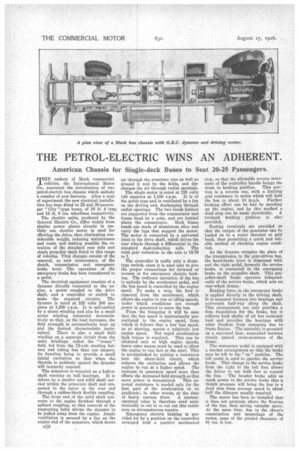
THE PETROL-ELECTRIC WINS AN ADHERENT.
Page 12
If you've noticed an error in this article please click here to report it so we can fix it.
American Chassis for Single-deck Buses to Seat 20-25 Passengers.
THE makers of Mack commercial vehicles, the International Motor Co., announce the introduction of two petrol-electric bus chassis which embody a number of new features. After a year of experiment the new electrical installation has been fitted to 25 and 20-passenger " City "-type buses, of 16 ft. 4 ins.. and 18 ft. 9 ins. wheelbase respectively.
The electric units, produced by the General Electric Co., differ widely from similar power plants already in use. Only one electric motor is used for effecting the drive, thus eliminating considerable weight, reducing maintenance and costs, and making possible the retention of the standard rear axle and single propeller shaft fitted to this range of vehicles. Vital changes consist of the removal, as now unnecessary, of the clutch, transmission and emergency brake lever. The operation of the emergency brake has been transferred to a pedal.
The electrical equipment consists of a dynamo directly connected to the engine, a motor coupled to the drive shaft, and a controller or switch to make the required circuits. The dynamo is rated at 125 volts 200 amperes at 1,200 r.p.m. It is self-excited by a shunt winding and also by a small series winding connected accumulatively so that, as the load increases, the field strength is automatically kept up and the desired characteristic maintained. There is also a small field winding on a separate circuit from the main windings, called the " teaser " field, fed from the 12-volt starting battery and taking fess than one ampere, its function being to provide a small initial excitation so that when the throttle is suddenly opened the dynamo will instantly respond.
The armature is mounted on a hallow shaft running on -ball bearings. It is driven by a smaller and solid shaft carried within the armature shaft and connected to the latter at the rear end through a rubber-block flexible coupling.
The front end of the solid shaft connects to the engine flywheel through a splined coupling, so that removal of the supporting bolts allows the dynamo to be pulled away from the engine. Ample ventilation is secured by a fan on the engine end of the armature, which draws
air through the armature core as well as around it and by the fields, and discharges the air through radial openings.
The single motor is rated at 125 volts 140 amperes at 1,100 r.p.m. It is of the series type and is ventilated by a fan on the driving end, discharging through radial openings. The two brush holders are supported from the commutator and frame head by a yoke, and are loehted above the commutator. Both frame heads are made of aluminium alloy and carry the lugs that support the motor. The motor is connected by a universal joint to the drive shaft, which drives the rear wheels through a differential in the standard dual-reduction axle. The total gear reduction in the axle is 10.79 to 1.
The controller is really only a drumtype switch, since it is used only to give the proper connections for forward or reverse or for emergency electric braking. The ordinary operation of the bus is entirely by the accelerator pedal, and the bus speed is controlled by the engine speed. To make a stop, the foot is removed from the accelerator, which allows the engine to run at idling speeds, under which conditions not enough power is generated to move the bus.
From the foregoing it will be seen that the bus speed is approximatly proportional to the engine speed, from which it follows that a low bus speed, as at starting, means a relatively low
engine speed. For rapid acceleration high torque is required. This can be obtained only at high engine speeds, hence some means must be used to allow the engine to run fast at the start. This is accomplished by putting a resistance into the shunt-field circuit, which reduces the excitation and allows the engine to run at a higher speed. The increase in generator speed more than offsets the decreased field strength so that more power is transmitted. This external resistance is needed only for the first part of the acceleration or on gradients ; in other words, at the time of heavy current draw. A currentoperated relay is therefore used automatically to cut in or cut out this resistance as circumstances require.
Emergency electric braking is provided for by a position on the controller arranged with . a positive mechanical stop, so that the allowable reverse move ment of the controller handle brings the drum to braking position. This posi
tion is a reverse one, with a limiting
grid resistance in series which will hold the bus to about 10 m.p.h. Further_ braking effort can he had by speeding up the, engine, and by this method a dead stop can be made electrically. A forward braking position is gs3 provided.
Testing terminals are provided so that the output of the generator can be loaded on to a water rheostat or grid bank, thus permitting a quick and reliable method of checking engine condition.
As the dynamo occupies the place of the transmission in the gear-driven bus, the hand-brake lever is dispensed with and the right pedal, formerly the service brake, is connected to the emergency brake on the propeller shaft. This propeller-shaft brake operates independently of the service brake, which acts on rear-wheel drums.
Braking force in the emergency brake is applied directly to the driving shaft.
It is mounted between two bearings and universals half-way along the shaft. This arrangement not only provides a firm foundation for the brake, but it relieves both shafts of all but torsional load and provides the bearings with utter freedom from cramping due toframe flexion. The assembly is mounted on a cast-steeI base, suspended between . closely spaced cross members of the frame.
The emergency pedal is equipped with a ratchet arrangement so that the brake may be left in the " on " position. The left pedal is used to operate the service brake. This change in the service brake from the right to the left foot allows the driver to use both feet to control the bus. The booster brake adds so
much power to the service brake that a thumb pressure will bring the bus to a dead stop from average speed in about half the distance usually required.
The motor has been so installed that it does not protrude above the flooring of the bus, thus saving valuable space. At the same time, due to the chassis construction and mountings of the motor, none of the ground clearance of 93: ins, is lost.