


Ferguson Transfer Box
Page 68
If you've noticed an error in this article please click here to report it so we can fix it.
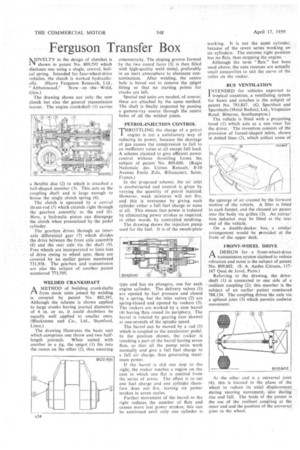
NOVELTY in the design of clutches is shown in patent No. 809,593 which discloses one using a single, central, helical spring. Intended for four-wheel-drive vehicles, the clutch is worked hydraulic
ally. (Harry Ferguson Research, Ltd., Abbotswood," Stow on -the Wold, Glos.) The drawing shows not only the new clutch but also the general transmission layout. The engine crankshaft (1) carries a flexible disc (2) to which is attached a ell-shaped member (3). This acts as the coupling shaft and is large enough to house the single clutch spring (4).
The clutch is operated by a central thrust-rod (5) which extends right through the gearbox assembly to the end (6). Here, a hydraulic piston can disengage the clutch wheri pressurized by the pedal cylinder. The gearbox drives through an interaxle differential gear (7) which' divides the drive between the front axle assembly (8) and the rear axle via the shaft (9). Free wheels are incorporated to limit loss of drive owing to wheel spin; these are covered by an earlier patent numbered 731,938. The gearbox and transmission are also the subject of another patent numbered 773,595.
WELDED CRANKSHAFT
PAA METHOD of building crankshafts from stock units joined by welding is covered by patent No. 802,591. Although the scheme is shown applied to large cranks having journal diameters of 6 in. or so, it could doubtless be equally well applied to smaller ones. (Blackstone and Co., Ltd., Stamford, Lincs.)
The drawing illustrates the basic unit which comprises one throw and two halflength journals. When united with another in a jig, the spigot (1) fits into the recess on the other (2), thus ensuring concentricity. The sloping groove formed by the two coned faces (3) is then filled with high-quality weld metal, preferably in an inert atmosphere to eliminate contamination. After welding, the centre hole is bored out to remove the spigot fitting so that no starting points for cracks are left.
Special end units are needed, of course; these are attached by the same method. The shaft is finally inspected by passing a gamma-ray source through the centre holes of all the welded joints.
PETROL-INJECTION CONTROL
THROTTLING the charge of a petrol engine is not a satisfactory way of reducing its power, because the shortage of gas causes the compression to fall to an inefficient value at all except full load. A scheme claimed to give efficient power control without throttling forms the subject of patent No. 809,600. (Regie Nationale des Usines Renault, 8-10 Avenue Emile Zola, Billancourt, Seine, France.) In the proposed scheme, the air, inlet is unobstructed and control is given by varying the quantity of petrol injected. However, weak mixtures will not fire, and this is overcome by giving each cylinder either a full fuel charge or none at all. This means that power is reduedby eliminating power strokes as required, in other words, by controlled. misfiring.
The drawing shows the injection piimp used for the fuel. It is of the swash:plate
type and has six plungers, one for each engine cylinder. The delivery valves (1) are opened by fuel pressure and closed by' a spring, but the inlet valves (2) are spring-closed and opened by rockers (3). The rockers are worked by a cam barrel (4) having flats round its periphery. The barrel is rotated by gearing (not shown) at one-seventh of the spindle speed.
The barrel can be moved by a rod (5) which is coupled to the accelerator pedal. In the position shown, the rocker is touching a part of the barrel having seven flats, so that all the pump units work normally and give a full fuel charge to a full air charge, thus generating maximum power.
If the barrel is slid one step to the right, the rocker reaches a region on the cam in which one flat is omitted from the series of seven. The effect is to cut one fuel charge and one cylinder therefore does not fire, leaving six power strokes in seven cycles.
Further movement of the barrel to the right reduces the number of flats and causes more lost power strokes; this can be continued until only one cylinder is working. It is not the same cylinder, because of the seven series working on six cylinders. The extreme right position has no flats, thus stopping the engine.
Although the term " flats " has been used above, the cam recesses are actually small concavities to suit the curve of the roller on the rocker.
BUS VENTILATION
I NTENDED for vehicles exported to
tropical countries, a ventilating system for buses and coaches is the subject of patent No. 795,807. (G. Sparshatt and Sparshatts (Metal Bodies), Ltd., Vespasian Road, Bitterne, Southampton.) The vehicle is fitted with a projecting hood (I) which acts as a sun visor for the driver. The invention consists of the provision of funnel-shaped inlets, shown in dotted lines (2), which collect some of the upsurge of air created by the forward motion of the vehicle. A filter is fitted to each funnel, and the cleaned air passes into the body, via grilles (5). An .extric-; tion inductor may be fitted the rear end of the vehicle.
On a double-decker, bus, .a similar arrangement would be ticovidecr at the front of the upper deck.
FRONT WHEEL DRIVE
A, DESIGN for a front-wheel-drive I-1 transmission system claifned to reduce vibration and noise is the subject of patent No. 809,602. (S. A. Andre Citroen, 117167 Quai de Javel, Paris.) Referring to the drawing, the driveshaft (1) is connected to one side of a resilient coupling (2); this member is thesubject of an earlier patent numbered 788,134. The coupling drives the axle via a splined joint (3) which permits endwise movement.
At the other end is a universal joint (4); this is located in the plane of the wheel to reduce its axial displacement, during steering movement, also during rise and fall. The basis of the patent is the use of the resilient coupling at the inner end and the position of the universal joint in the wheel.