


A NEW VULCAN 36-SEATER BUS CHASSIS.
Page 58
Page 59
Page 60
If you've noticed an error in this article please click here to report it so we can fix it.
Full Details of a Six-cylinder Low-loading Chassis Built to Suit the Demands of Corporation Authorities and Private Enterprises.
ECENTLY the Vulcan Motor Engineering Co., Ltd., J11.)delivered the lust of a series of 36-seater single-deck omnibuses to the Southport Corporation for use in and around the town. These vehicles are of more than ordinary interest, for, besides a generally interesting specification for all the main components, the layout of the transmission incorporates a free-wheel device. For town work, of course, this device should assist materially in keepine; down run-. ning costs and add greatly to the sweet running characteristics of the chassis. Further, by virtue of the interruption in the drive—allowing the rear axle and propeller shaft to overrun the engine and gearbox—gear-changing should be rendered easier and more silent in operation, without requiring the driver to possess any .great skill or facility for the nice handling of a gearbox.
In practice, when taking a corner, for instance, the vehicle must necessarily be slowed down,; consequently the driver's foot is removed from the accelerator and the engine allowed merely to "tick over" (the free wheel being in operation). When this state of affairs exists it is possible to shift the gear from, say, "top ' and to engage "second" without using the clutch and without the slightest noise emanating from the meeting of the pinions. The reason for this, of course, is that the engine and consequently the gearshafts are revolving at very low speeds indeed, the only load upon the teeth being that due to the inertia of the shaft and pinions, a force that is, of course, almost negligible at low speeds.
• It will be seen, then, that when approaching a corner, the driver would commence to slow down when perhaps 200 yards away from the actual turn and, allowing a few seconds for the engine speed to die down to the " ticking-over " speed, the driver could, without touching the clutch pedal, change from 'fourth to second speed and so be ready for immediate acceleration when the corner
is reached. This Vulcan free-wheel device has already been described in The Commercial Motor, but we have reiterated the main features so that readers will be able to appreciate one of the most interesting characteristics of the chassis which we are about to describe.
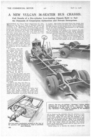
In the forefront of the minds of the designers the question of overloading has obviously been clearly considered. Although nominally possessing a capacity for 36 passengers, this new Vulcan bus can, withont harm accruing, be loaded up to almost twice that amount. This is not, however, a practice to be recommended, but anyone making a study of the general layout of the frame and, indeed, all the major components,
will be forced to the conclusion that the statement is not unwarranted. The frame, for instance, is no less than 31 ins, deep, despite the fact that the wheelbase is no longer than 17 ft. 6 ins, and the load is supported at eight points on semi-elliptic springs. There is a considerable kick-up over both front and sear axles, the arch in the frame at the rear being about 11 ins. high ; the upswept portion at the front runs parallel with the upper face of-the main portion of the frame. .
Beforegoing on to describe the chassis it would seem
opportune to quote a few dimensions concerning the space available for seating accommodation, overall length, etc. With 34-in. by 7-in. tyres, the height to the top of the frame
is 25 ins. a minimum of ground clearance being provided beneath the underslung worm casing of the rear axle. The overall length of the chassis is 26 ft. 1 in., whilst the distance from the back of the driver's seat to the rear of the chassis provides a body space of practically 20 ft. 11 ins.— no mean achievement, considering the fact that a comparatively large six-cylindered engine is installed with very little overhang beyond the front wheels. These dimensions have enabled 36 seats to be arranged without cramping and in a body incorporating two doors. Incidentally, the chassis weighs 3 tons and the body approximately 2 tons, making the unladen weight of the complete vehicle approximately 5 tons. With wheel tracks of 5 ft. 114 ins. and 5 ft. 9 ins. front and rear respectively, a 60-ft. turning circle is obtained.
Dealing now with the chassis in more detail, the engine is supported in the frame at three points from a sub-frame which is formed of two channels, attached at the front to a half-loop cross-member running beneath the radiator and supported at the rear by a trunnion-block located between the clutch-withdrawal race and the front universal joint. This sub-frame incorporates the mounting for the clutch actuation, and so makes the two components, the engine and clutch, into a unit.
The engine has six cylinders of 100 mm. bore and 140 ram. stroke, which gives an R.A.C. rating of 37.2 h.p. On the test bench it develops 48 b.h.p. at 1,000 r.p.m. and 80 Ith.p. at 2,000 r p.m. The cylinders are formed monobloc in a clean-looking casting, which is bolted 'to an aluminium crankcase; this latter component, being well ribbed and of • deep section, forms a rigid mounting for a four-bearing , crankshaft. side-by-side valves are employed ; they are • operated by mushroom-type tappets from a one-piece cam. shaft, supported, like the crankshaft, in four main bearings and driven by silent chain from the forward end of the crankshaft. The valves, incidentally, are totally enclose,d by quickly detachable covers, so that they (the valves) operate in an oil mist, but are readily get-at-able when tappet adjustment becomes necessary. A detachable cylinder head Is secured to the top of the cylinder block by a number of substantial and well-placed bolts. They shonld, therefore, give no trouble in practice by stripping threads or breaking off when the head has to be removed for decarbonizatioe, valve grinding, etc. All the combustion chambers are of the Ricardo turbulent type.
At the forward end of the engine a cross-shaft is driven by spiral spur gears, the water pump being located on the off side and the magneto on the near side extremity of the shaft.
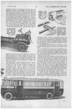
It is interesting to note that all the auxiliaries are grouped on the near side of the engine in order to facilitate
maintenance work—the chassis is equipped with forward steering. Thus, the carburetter, oil filter and filler spout, inlet and exhaust manifolds and magneto are all conveniently placed and areeasily accessible merely by lifting the bonnet on the near side.
Turning now to the lubrication system, the sump is an aluminium casting with a capacity for three gallons of oil.
At the lowest point there is a gear-type pump, which is driven by spiral gears from the camshaft. Oil is forced to each of the four main bearings of both the camshaft and crankshaft, thence to each of the six big-end bearings of the connecting rods via ducts drilled in the crankshaft. A feature of interest to the user is the fact that a filter is located on the suction side of the pump which excludes all solid matter from the bearings, whilst, in addition, all impurities are collected in a well which can be drained by
removing a plug. Further, a detachable filter is incorporated on the delivery side, thus making doubly sure that the lubricant is perfectly clean before it gets to the bearings. An oil level indicator is fitted on the near side of the engine.
A multiple dry disc, self-contained clutch is fitted unitwise with the engine. The friction fabric is Raybestos, and there are four driving plates, whilst the springs are operated through toggle levers in order to give a very light pedal pressure. A clutch stop of the ordinary disc type is fitted between the front universal joint housing, and the clutch withdrawal race.
From the clutch a universally jointed propeller shaft conveys the drive to a four-forward-speed gearbox. The ratios of the box are :—Top, 1 to 1; third, 1.55 to 1; second, 2.71 to 1; and bottom, 5.34 to 1. The standard rear axle ratio is 6.25 to 1, but there are alternative ratios of 51 64 or 7 to 1, for which an extra charge is made. Using the 6.25 to 1 rear axle reduction gears the overall ratios work out at approximately :—Top, 6.25 to 1; third, 9.65 to 1; second, 17 to 1; and bottom, 33.5 to 1.
In the interests of silence the shape of the gear-teeth has been altered from the stub type (which has previously been Vulcan practice) to No. 6 normal teeth. The main shafts are of large diameter, the secondary shaft being fitted with an intermediate bearing. Attached to the back of the-gearbox is the free-wheel device, the transmission to the rear axle consisting of a two-stage, universally jointed propeller shrft. In passing it might be mentioned that the method of housing the intermediate bearings in the transmission is distinctly interesting and forms the subject of a drawing.
The type of free-wheel device employed on the Vulcan chassis was fully described in the issue of The Commercial Motor for January 10th, 1928. It is quite simple, consisting of a multiple roller free-wheel clutch employed to transmit the forward drive and to permit the propeller shaft (and with it the final drive to the wheels) to overrun the gearshaft when the vehicle is allowed to "coast." A ring having positive-locking buttressed teeth is operated by a lever fork
and collar to give a bi-directional drive whenever required.
The rear axle is of the fully floating type, and consists of a one-pieee, 40-ton, steel-pot type stamping carrying the underslung worm-and-wheel reduction gear. A bevel-type differential is contained in a separate housing which can be easily removed without disturbing the axle casing. The worm shaft runs in ball bearings, and a large double-thrust washer is provided to take care of end thrust.
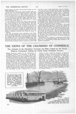
The steering gear is mounted on the extreme forward end of the frame side-member, so that the driver can be accommodated beside the engine. The steering column is rafted at a comfortable angle. The brake connections and the controls are brought to the outside of the frame members so that the work of maintenance may be facilitated.
Front-wheel brakes are fitted as standard. The pedal operates through the medium of a vacuum servo motor and applies internal-expanding shoes within drums attached to both front and rear axles. A hand-brake operates, in the ordinary manner, on a separate pair of internal-expanding shoes on the rear wheels only. As already stated, the tyres are of 34-in, by 7-in. section. They are mounted on steel disc-type wheels attached to the hubs by eight bolts; singles are fitted at the front and twins at the rear. Fuel is fed to the engine from a 35-gallon tank slung at the rear of the chassis, via an Autovae. There is a Hobson Telegauge fitted to the dash.
Equipment is very complete • a speedometer, spare wheel and tyre, 12-volt five-lamp lighting set, electric and bulb horns and a mechanical-type pump being included in the standard specification.