


AN INFINITELY-VARIABLE HYDRAULIC GEAR.
Page 22
If you've noticed an error in this article please click here to report it so we can fix it.
A Resume of Recently Published Patent Specifications.
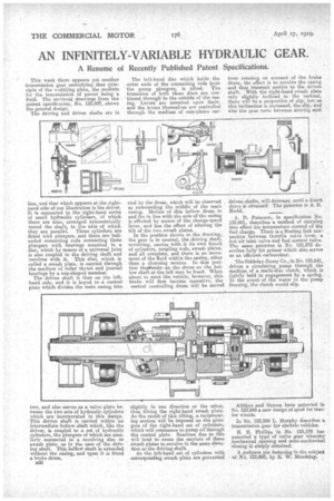
This week there appears yet another transmission gear embodying that -principle of the wobbling plate, the median.' for the transmission of power being a fluid. The sectional, drawings from the patent specification; No. 123,607, shows the general design..
The driving and driven shafts are in line, and that which appears at the righthand side of our illustration is the driver. It is connected to the right-hand series of small hydraulic cylinders, of which there are nine, arranged symmetrically round the shaft, to the axis of which they are parallel. Them cylinders are fitted with plungers, and there are ballended connecting rods connecting these plungers with bearings mounted in a disc, which by means of a universal joint is also coupled to the driving shaft and revolves with it. This disc, which is called a awash plate, is carried through the medium of roller thrust and journal bearings by a cup-shaped member. The driven shaft is that on the lefthand side, and it is keyed to -a central plate which divides the main casing into
two, and also serves as a valve plate between the two sets of hydraulic cylinders which are incorporated in this design. This driven shaft is carried within an intermediate hollow shaft which, like the driver, is coupled to a sot of hydraulic cylinders, the plungers of which are siznilarly connected to a revolving disc or awash plate, as in the ease of the driving shaft. This hollow shaft is extended without the casing, and upon it is fitted a brake drum.
B50
The left-hand disc which holds the outer ends of the connecting rods from the pump plungers, is tilted. The trunnions of both these discs are continued through' to the outside of the easing. Levers are mounted upon them, and the levers themselves are controlled through the medium of cam-plates car
Tied by the drum, which will be observed as surrounding the middle of the main casing. Motion of this hollow drum to and fro in line with the axis of the casing is effected by means of the change-speed lever, and has the effect of altering the tilt of the two swash plates. In the position shown in the drawing, the gear is in neutral, the driving shaft, revolving, carries with it its own bunch of cylinders, coupling rods, awash plates, and all complete, and there is no movement of the fluid within the easing, other than a churning motion. In this position thesshrake on the drumon the hollow shaft at the left may be freed. When about to start the vehicle, however, this brake will first become operative, the central controlling drum will be moved
slightly in one direction or the other, thus tilting the right-hand swa,sh plate. As the result of this tilting, a reciprocating motion will be imposed on the plangers of the right-hand set of cylinders, which will commence to pump oil through the central plate. Reaction due to this will tend to cause the carriers of these awash plates to revolve in the same direction as the driving shaft. As the left-hand set of cylinders -with corresponding awash plate are prevented
from rotating on account of the brake drum, the effect is to revolve the casing and thus transmit motion to the driven. shaft. • With the right-hand awash plate only slightly inclined to the vertical, there will be a proportion of slip, but as this inclination is increased, the slip, and also the gear ratio between driving and driven shafts, will decrees°, until a direct drive is obtained: The patentee is A. E. Hudd.
A. D. Paterson, in specification No. 123,601, describes a method of carrying into effect his temperature control of the fuel charge. There is a floating link connection between throttle valve lever, a hot air inlet valve and fuel control valve, The same patentee in No. 123,572 describes fully his primer which also serves as an efficient carburetter.
The Siddeley-Deasy Co., in No. 123,641, drives a circulating pump through the medium of a multi-dise clutch, which is lightly held in engagement by a spring. In the event of the water in the pump freezing, the clutch would slip.
Allda,ye and Onions have patented in No. 123,643 a new design of spud for tractor wheels.
In No, 123,554 L. Murphy describes a transmission gear for electric vehicles.
H. E. Phillips in No. 123,578 has patented a type of valve gear whereby mechanical opening and semi-mechanical closing is simply obtained.
A gudgeon pin fastening is the subject of No. 123,805, by IL W. Mandalay. .