SIMPLE MECHANICS
Page 84

Page 85

If you've noticed an error in this article please click here to report it so we can fix it.
Steering geometry 2
by Preceptor
A WELL-DESIGNED steering system will always tend to maintain the vehicle on a straight course, saving the driver from constantly having to correct it wandering from side to side. The steering should also straighten out, or self centre, automatically, after turning a corner. The self-centring effect has to be overcome by the driver whenever he wants to change direction and this enables him to "feel" his steering.
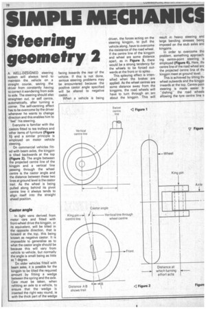
Everyone is familiar with the castors fitted to tea trolleys and other items of furniture (Figure 1) and a similar principle is employed on motor vehicle steering.
On commercial vehicles fitted with beam axles, the kingpin is tilted backwards at the top (Figure 2). The angle between the projected centre line of the kingpin and a vertical line passing through the wheel centre is the castor angle and the distance between these two lines at ground level is the castor trail. As the wheel is being pulled along behind its pivot centre line it always tends to align itself into the straight ahead position.
Castor angle
In light vans derived from motor cars and fitted with front-wheel drive the kingpin, or its equivalent, will be tilted in the opposite direction, that is forward at the top, this being known as negative castor. It is impossible to generalise as to what the castor angle should be because this will vary from vehicle to vehicle, but normally the angle is small being as little as 1 degree.
On older vehicles fitted with beam axles, it is possible for the kingpin to be tilted the required amount by fitting a wedge between the spring and the axle. Care must be taken, when refitting an axle to a vehicle, to ensure that the wedge is inserted the right way round, ie with the thick part of the wedge facing towards the rear of the vehicle. If this is not done, serious steering problems may be encountered because the positive castor angle specified will be altered to negative castor.
When a vehicle is being driven, the forces acting on the steering kingpin, to pull the vehicle along, have to overcome the resistance of the road wheel. If the centre line of the kingpin and wheel are some distance apart, as in Figure 3, there would be a strong tendency for the wheels to be forced outwards at the front or to splay.
This splaying effect is intensified when the brakes are applied. As the wheel centres are some distance away from the kingpins, the road wheels will have to turn through an arc about the kingpin. This will result in heavy steering and large bending stresses being imposed on the stub axles and kingpins.
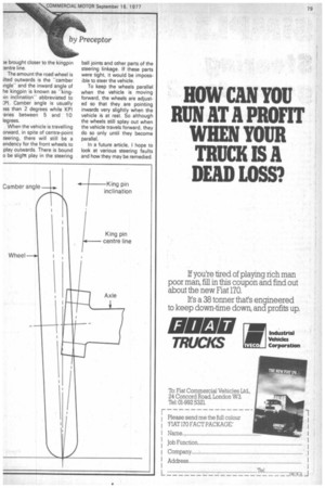
In order to overcome this problem, something approach. ing centre-point steering is employed (Figure 4). Here, thc centre line of the road wheel an the projected centre line of th( kingpin meet at ground level.
This is achieved by tilting th( wheel outwards and the kingpir inwards at the top. Centre-poin steering is made easier IT "dishing" the road wheels allowing the tyre centre line ti )e brought closer to the kingpin ;entre line.
The amount the road wheel is ilted outwards is the "camber Ingle" and the inward angle of he kingpin is known as "king)in inclination" abbreviated to Camber angle is usually ass than 2 degrees while KPI ,aries between 5 and 10 legrees.
When the vehicle is travelling orward, in spite of centre-point ;teering, there will still be a endency for the front wheels to ;play outwards. There is bound o be slight play in the steering ball joints and other parts of the steering linkage. If these parts were tight, it would be impossible to steer the vehicle.
To keep the wheels parallel when the vehicle is moving forward, the wheels are adjusted so that they are pointing inwards very slightly when the vehicle is at rest. So although the wheels still splay out when the vehicle travels forward, they do so only until they become parallel.
In a future article. I hope to look at various steering faults and how they may be remedied


