


A Self-energizing Disc Brake
Page 64
If you've noticed an error in this article please click here to report it so we can fix it.
1"1-1E capacity of the usual three I hydraulic cylinders of a disc brake approaches the limit of volume that the master cylinder can supply, and there are physical limitations which preclude the use of bigger master-cylinders.
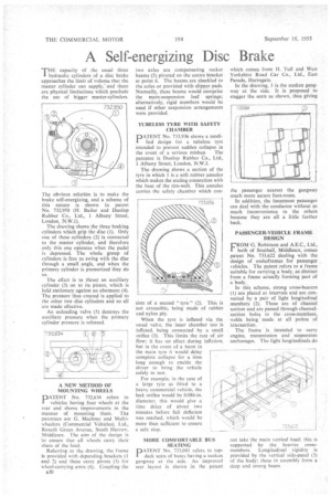
The obvious solution is to make the brake self-energizing, and a scheme of this nature is shown in patent No. 732,950 (H. Butler and Dunlop Rubber Co., Ltd„ 1 Albany Street, London, N.W.I).
The drawing shows the three braking cylinders which grip the disc (1). Only one of these cylinders (2) is connected to the master cylinder, and therefore only this one operates when the pedal is depressed. The whole group of cylinders is free to swing with the disc through a small angle, and when the primary cylinder is pressurized they do so.
The effect is to thrust an auxiliary cylinder (3) on to its piston, which is held stationary against an abutment (4). The pressure thus created is applied to the other two disc cylinders and so all are made effective.
An unloading valve (5) destroys the auxiliary pressure when the primary cylinder pressure is released.
A NEW METHOD OF MOUNTING WHEELS pATENT No. 732,634 refers to vehicles having four wheels at the rear and shows improvements in the manner• of mounting them. The patentees are G. Machray and Multiwheelers (Commercial Vehicles), Ltd., Roxeth Green Avenue, South Harrow, Middlesex. The aim of the design is 'to ensure that all wheels carry their share of the load.
Referring to the drawing, the frame is provided with depending brackets (I and 2) and these carry pivots (3) for wheel-carrying arms (4). Coupling the
B30 two axles are compensating rocker beams (5) pivoted on the centre bracket at point 6. The beams are shackled to the axles or provided with slipper pads. Normally, these beams would comprise the main-suspension leaf springs; alternatively, rigid members would be used if other suspension arrangements were provided.
TUBELESS TYRE WITH SAFETY CHAMBER
DAT-ENT No. 733,936 shows a modified design for a tubeless tyre intended to prevent sudden collapse in the event of a serious mishap. The patentee is Dunlop Rubber Co., Ltd., 1 Albany Street, London, N.W.1.
The drawing shows a section of the tyre in which 1 is a soft rubber annulus which makes the scaling connection with the base of the rim-well. This annulus carries the safety chamber which con sists of a second "tyre" (2). This is not extensible, being made of rubber and nylon ply.
When the tyre is inflated via the usual valve, the inner chamber too is inflated, being connected by a small orifice (3). This limits the rate of air flow; it has no effect during inflation, but in the event of a burst in the main tyre it would delay complete collapse for a time long enough to enable the driver to bring the vehicle safely to rest.
For example, in the case of a large tyre as fitted to a heavy commercial vehicle, the • leak orifice would be 0.086-in. diameter; this would give a time delay of about two minutes before full deflation was reached, which would be more than sufficient to ensure a safe stop.
MORE COMFORTABLE BUS SEATING
PATENT No. 733,081 refers to topdeck seats of buses having a sunken gangway at the side. An improved seat layout is shown in the patent
which comes from H. Tuff and West Yorkshire Road Car Co., Ltd., East Parade, Harrogate.
In the drawing, 1 is the sunken gangway at the side. • It is proposed to stagger the seats as shown, thus giving
the passenger nearest the gangway much more secure foot-room.
In addition, the innermost paSsenger can deal with the conductor without so much inconvenience to the others because they are all a little farther back.
PASSENGER-VEHICLE •FRAME DESIGN
FROM G. Robinson and A.E.C., Ltd., both of Southall, Middlesex, comes patent No. 733,622 dealing with the design of underframes for passenger vehicles. The patent refers to a frame suitable for carrying a body, as distinct from a frame actually forming part of a body.
In this scheme, strong cross-bearers (I) are placed at intervals and are connected by a pair of light longitudinal members (2). These are of channel section and are passed through channelsection holes in the cross-members, welds being made at all points of intersection.
The frame is intended to carry• engine, transmission and suspension anchorages. The light longitudinals do
not take the main vertical load: this is supported by the heavier cross
members. Longitudinal • rigidity is provided by the vertical side-panel (3) of the body; these in assembly form a deep and strong beam.