


A Compression Controlled injector
Page 56
If you've noticed an error in this article please click here to report it so we can fix it.
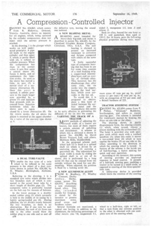
PATENT No. 624,843, which comes from R. Blakeway, Ormond, Victoria, Australia, shows an injector for oil engines, which, being operated by the cylinder compression, does not inject until the correct pressure is reached.
In the drawing, 1 is the plunger which works on well understood principles. A pipe (2) leads to the engine cylinder and thus space 3, which is partly filled with oil, is subject to cylinder pres-sure. When the compressionhas risen to the correct value, it acts first upon a central sleeve (4), forces it down. and so commences the injection stroke. As soon as the-sleeve has moved a little, its port (5) is moved clear of a stationary obstruction (6). Once this port is opened, it admits pressure to the much larger area provided by a piston (7) and injection then proceeds with increased force. Injection terminates when the sleeve port is again closed by a lower obstruction (8). On the return stroke, the oil above the pis:tort is returned to the ,upper chamber Via a valve of the one-way type shown at 9.
A DUAL TYRE-VALVE
TO enable the two tyres of a twin wheel to be inflated to the same pressure is the object of a dual tyrevalve shown in patent No. 624,186, by H. Wheeler, Birmingham, Alabama, U.S.A.
Referring to the drawing, I is a standard tyre valve which divides into two branches each of which is connected to the actual inner tube by a short length of flexible pipe (2). The composite valve is preferably located on the hub cap for reasons of balance.
In the lower passage is a doubleended rubber plug (3) which normally is held in the middle of its casing by a lightly spring-loaded pin (4). During inflation, the air divides evenly between the two branches, as there is no obstruction. But if one tyre be suddenly deflated, the rush of air from one side to the other would blow the rubber plug to one side and so seal off A38 the defective tyre, leaving the sound one isolated. '
A NEW BEARING METAL. BEARING metal intended for heavy-duty big-ends and mains is described in patent No. 624,401, by the Cleveland Graphite Bronze Company, Cleveland, Ohio, U.S.A. The new bearing is claimed to possess an increased resistance to corrosion and fatigue compared with others of the same type.
A fairly successful type of composite bearing that has been in use for some time consists of a steel backing strip, a copper-lead .intermediate layer, and an overlay of titaLlead alloy.
• This, however, has the disadvantage that, after some time, the tin works into the copper, leaving the lead surface, which soon corrodes in the hot oil.
To avoid this it is proposed to electroplate a thin layer of nickel between the surface metal and the intermediary; this seems to be quite effective in preventing the diffusion of the tin into the copper. VARYING THE TRACK OF A TRACTOR
NAANY methods of adjusting the aloverall width of a tractor are known, but most of them require a certain amount of unbolting and detachment. A scheme in which this is obviated is shown in patent No. 624,980, by David Brown Tractors, Ltd. and others, Meltham Mills, Huddersfield.
In the proposed scheme each wheel hub (1) is fixed to a splined shaft (2) which is driven by anenclosing sleeve (3) carrying a gearwheel (4). The adjustment for track width is made by sliding the splined shaft in or out of its sleeve; this is performed by a long screw (5) that can he rotated from the outside, without the need for any dismantling. When adjusted, the position is fixed by a locking screw (6).
A NEW ALUMINIUM ALLOY
FROM R.. Bradbury, 57, Windley 1 Crescent, Darley
Abb ey, Derby, comes patent No. 624,955, describing a new aluminiumbased alloy. This alloy,' intended mainly for forgings, is stated by the inventor to possess maximum stress, proof stress and hardness values.
Several formula are mentioned, a typical one having, in addition to the aluminium, the following percentages of other metals: zinc 7.8, magnesium 3.1, nickel 3, manganese 1.5, iron .2 and silicon .2.
Such an alloy, heated for one hour at 520 C. and quenched, then aged at 130 C. for 16 hours, gave the following physical properties during tests: maxi mum stress 45 tons per sq. in,, proof stress (.1 per cent.) 42 tons per sq. in., with an elongation of 9.5 per cent, and a Brinell hardness of 225.
TRACTOR STEERING SYSTEM
.PATENT No. 623,834 comes from F. Pinhay, "Ellisland," Baddesley, Southampton, and refers .to tractor steering gear. The scheme is intended for tracklayers steered. by braking the drive on one side or the other.
The drawing shows, in partly diagrammatic form, the steering column (1) which, when turned, rotates a pinion meshing with the crownwheel (2). Thefl latter is provided also with spur: gear teeth which mesh with .a toothed quadrant (3); vvhen this rocks it moves a two-armed lever (4) which in turn applies the brakes (5) on one side or the other, according to the direction in which the steering wheel is turned. A feature of the scheme is the lavish use of ball-bearings, a factor making for quick and easy operation. According to the inventor, this system of steering provides an improved response to hand control. It permits of a full-lock steering gear, enabling a tractor to be turned in a small circle, as opposed to steering of the-three-quarterlock type.
A safety-stop device is provided which limits the rotation of the steering wheel to a half-turn, right or left, so that a turn from one extreme position to the other is obtained with one complete turn of the steering wheel.