


Valve Location in Oil Engines
Page 54
If you've noticed an error in this article please click here to report it so we can fix it.
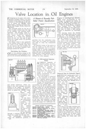
A Resume' of Recently Published Patent Specifications
I N designing an oil engine with rocker operated overhead valves, it is often a problem to find space for the injector. A solution of this difficulty is the subject of patent No. 489,995, which comes from L. Gardner and Sons, Ltd., Barton Hall Engine Works, Patricroft, Manchester.
The proposals made are the use of valves in pairs, located near the edge of the cylinder, and operated simultaneously. The drawing, which is a plan view of the scheme, shows the twin, valves which are operated primarily by a small arm, pivoted about the pin (4); this arm is itself moved by a larger rocker (1) pivoting on the pin (2).
The design, which is also applicable to the exhaust valves, not only leaves the centre of the cylinder head clear for the injector (3) but simplifies the problem of providing adequate water passages around the valves.
Non-fouling Gas Producer.
nNE of the problems arising in the construction of gas producers is to prevent the unwanted distillation of tar
and similar substances, which condense in the valve passages and cause fouling of the engine. A producer, claimed to be free from this defect, is shown in patent No. 489,640 (void), by Dr. W.
Koster, Solm strass e, 2, Frankfurt, Germany.
In the drawing, which shows a downdraught producer, air enters the central tube (1), and, passing down, reaches the zone of com bustion (2). From this point the gas descends through a reducing mixture (3) and leaves via a grate and the pipe (4).
The dow ndraught construction causes the distillation products to ri44 gravitate into the combustion zone, where they are broken up chemically and help to form the combustible mixture.
An essential feature of the patent is that the height of the inlet tube (1) must be adjustable; this is to accommodate fuels of varying composition. Another point is that, for starting purposes, the zone of combustion must be initiated with a small quantity of charcoal, otherwise a little tar would be distilled for a *few minutes.
A Self-contained Injection Pump.
ACOMPACT assembly of injection pump, governor, automatic advance and fuel feed-pump is disclosed in patent No. 489,817, by Scintilla. Ltd., of Soleure, Switzerland. The object of the design is to minimize the piping arrangement, in addition to saving space.
The drive-shaft is connected to the camshaft of the pump by a helically splined coupling (4), which serves to adjust the timing. This mechanism is controlled by a tubular piston (3)
surrounding the splined shaft. The piston is moved by oil pressure -from the gear pump (2), the force produced being proportional to the speed of the engine. The gear pump performs a triple function. It draws in fuel and feeds it to the pump supply channel (1), and, further, it acts as the motive power for operating both the timing adjustment and the speed governor. The latter device is shown at the left of the unit, and, comprises a springloaded piston (6), operating the rackrod of the pump via a bell-crank (5).
Progress in Centrifugal-type Clutches.
THE latest developments in the J. design of clutches are shown in patent No. 489,780, which comes from C. Higgs and the Borg and Beck Co., Ltd., both of Brock House, Langham Street, London, W.1. The patent deals with clutches of the semi-centrifugal type, in which a light springpressure is intensified by centrifugal action.
The drawing shows the friction plates, the pressure plate and the usual springs (1). The last-named, instead of abutting on the casing, are held in cups (2), attached to weighted levers (3). These levers are pivoted on a ring, fixed to the casing, and, when revolved at speed, move inwards and so increase the spring pressure. The patent is based more upon constructional detail than upon the main principle, which is already incorporated in some clutches.
Improved Ram for Hydraulic Tippers.
HYDRAULIC tipping gears must, of necessity, be provided with an automatic pressure release which operates when the piston reaches its limit, and patent No. 489,663 shows a device of this type which is claimed to avoid
stressing the mechanism. The patentee is the Clayton Dewandre Co., Ltd. and others, of Titanic Works, Lincoln.
The drawing shows part cf the inner cylinder of a telescoping pair, in which the piston (3) of the ram slides. The ram is shown in its fully extended position, in which the release valve (2) is forcibly opened by pressure upon a crossbar (1) which meets a sleeve (4) located in the cylinder end. Once the valve is opened, the oil passes freely upwards and escapes via an annular space leading the return pipe (not shown).